The 6-Pack Panel
Christopher Edwards
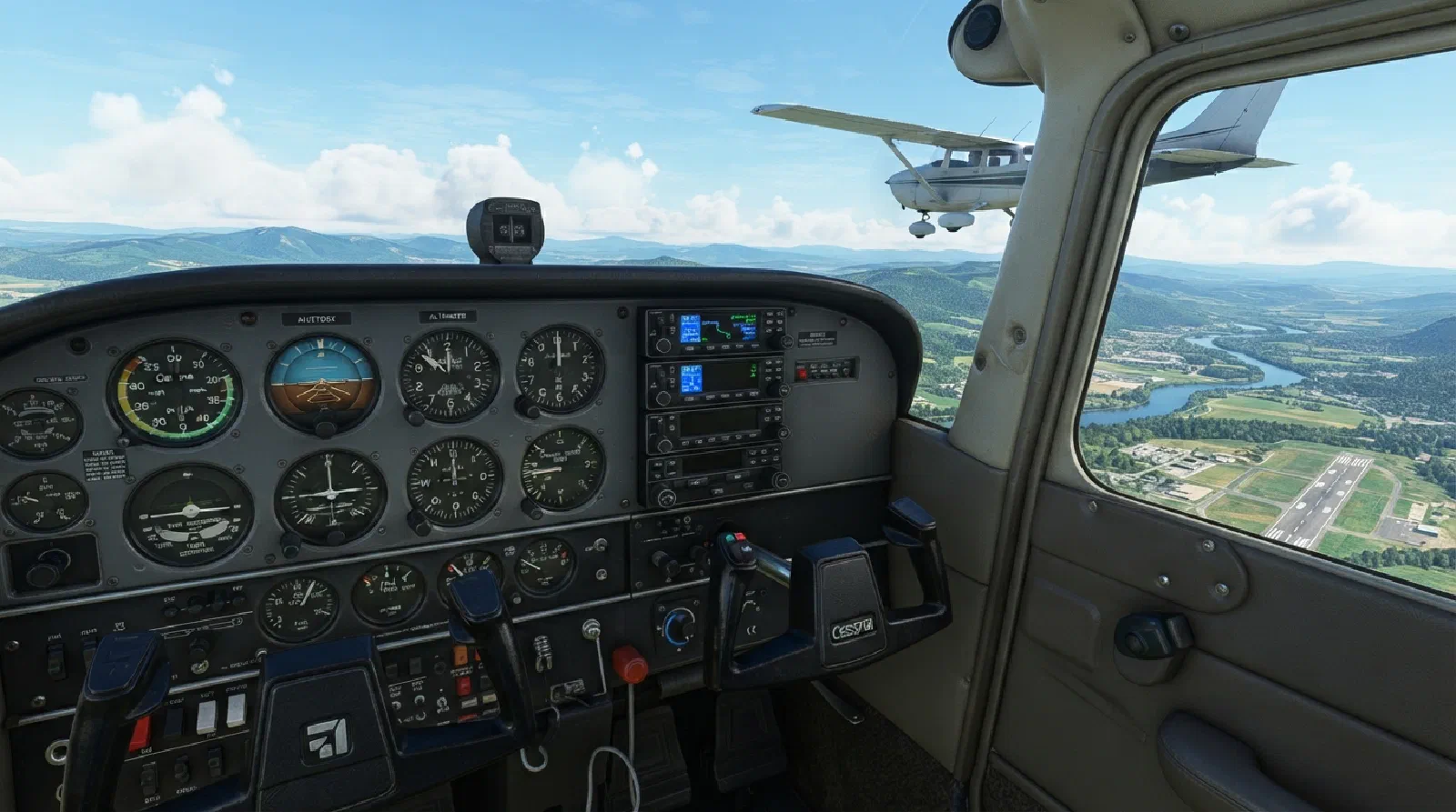
Cessna 172 Six-Pack: Building a Physical Panel Overlay
As part of my Cessna 172 flight simulator project, I wanted to start with something relatively contained: recreating the C172 instrument panel around a physical overlay.
The idea sounds straightforward. Put the instruments on a monitor, build a panel around them, and add the physical controls needed to interact with them.
In practice, the display isn’t the difficult part.
The difficult part is figuring out how to turn a flat computer monitor into something that actually feels like an instrument panel.
Starting With the X-Plane C172
For this project, I’m using the default Cessna 172 in X-Plane 12 as the baseline for the simulator.
Rather than trying to reproduce some generic “Cessna 172” panel, I wanted the simulator to correspond to the aircraft configuration I’m actually flying in the simulator.
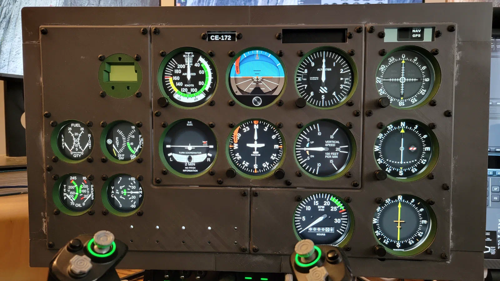
The primary flight instruments are based on the six-pack arrangement shown in the X-Plane C172:
- Airspeed Indicator
- Attitude Indicator
- Altimeter
- Turn Coordinator
- Heading Indicator
- Vertical Speed Indicator
The panel also includes the secondary instruments and engine indications surrounding the six-pack.
The C172 panel used as the reference for the physical layout.
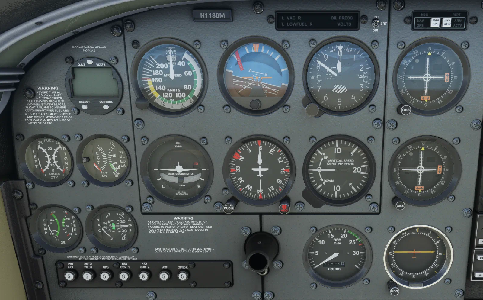
This gives me a specific configuration to work from rather than trying to design a generic C172 panel.
There are obviously many different C172 configurations in the real world. Instrument layouts can vary depending on the aircraft, its age, and subsequent avionics upgrades.
For this project, that variation isn’t a problem. The goal is to create a simulator around a specific reference configuration.
Using Air Manager for the Prototype
For the initial prototype, I’m using Air Manager to provide the instrument displays.
One of the advantages of this approach is that I don’t need to develop the instrument software myself.
Air Manager handles the instrument displays and provides the interface to the simulator, while I can concentrate on the physical side of the project.
The Raspberry Pi is used as the hardware platform for the Air Manager setup. Air Manager is flashed onto the Raspberry Pi, providing the software environment needed for the displays.
That means there isn’t a separate software-development effort for this part of the prototype.
Instead, I’m able to concentrate on the mechanical design and physical controls.
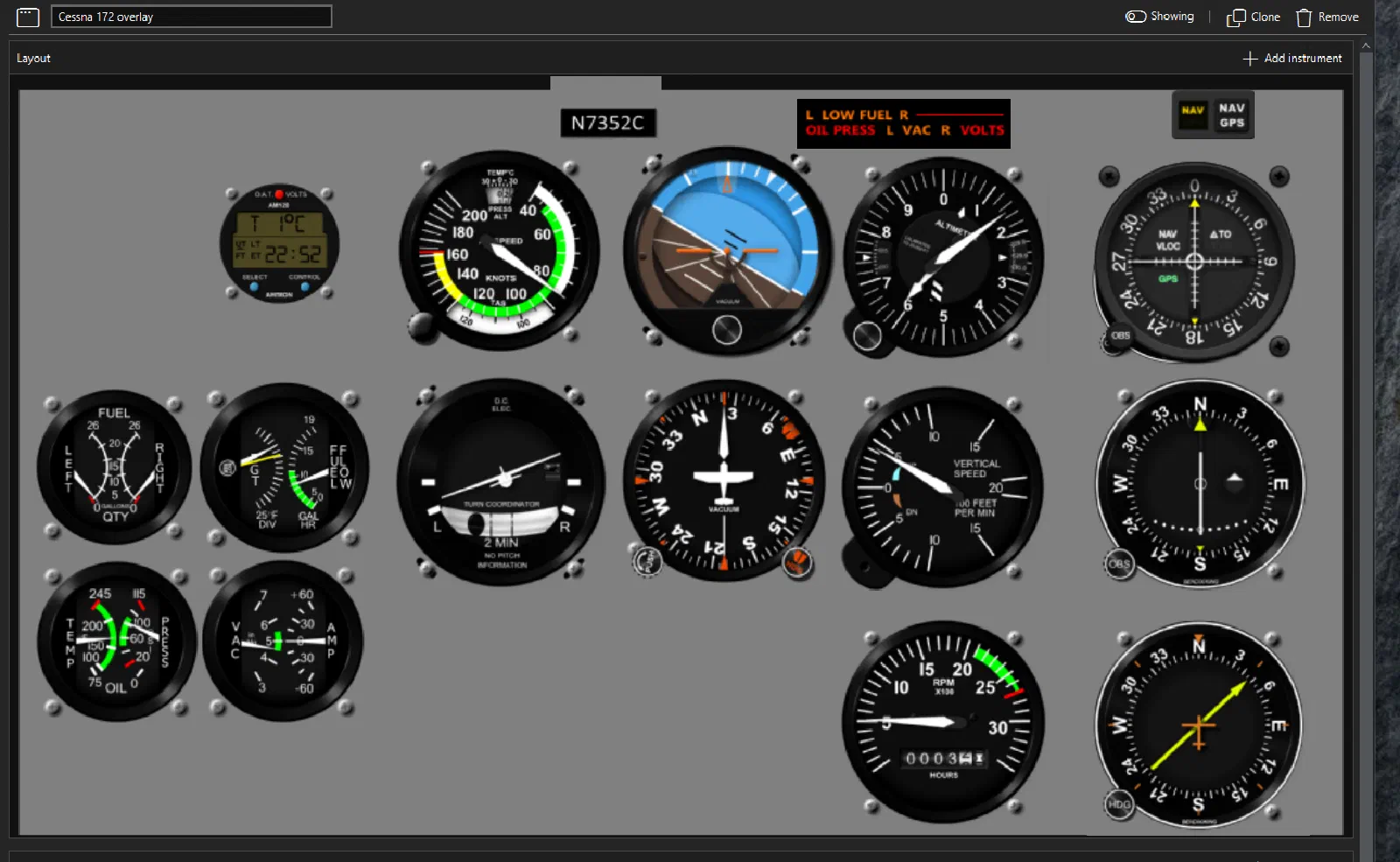
The Monitor Isn’t the Problem
Getting the six-pack and secondary instruments onto a screen is relatively easy.
The problem starts when you try to interact with them.
A mouse can turn a virtual knob, but that’s not how I want to operate the simulator.
When flying an actual aircraft, I don’t have to look at a screen and move a cursor to find the altimeter setting or heading adjustment. My hand goes to the control.
That’s the experience I’m trying to reproduce.
The monitor provides the visual information, but I want the physical panel to provide the interaction.
This led to the basic architecture for the prototype:
Monitor
→ Displays the simulated primary and secondary instruments
Physical Overlay
→ Provides the instrument openings, bezels, knobs, and buttons
Raspberry Pi / Air Manager
→ Provides the instrument display system
The physical panel essentially becomes a bridge between the simulated cockpit and the real world.
The Overlay Panel
The biggest engineering challenge is the overlay itself.
The panel needs to sit directly in front of the monitor while allowing the simulated instruments to remain visible through openings in the physical panel.
And because the panel includes both the six-pack and the surrounding secondary instruments, there are considerably more details to account for than just six circular cutouts.
CAD model showing the primary and secondary instrument locations.
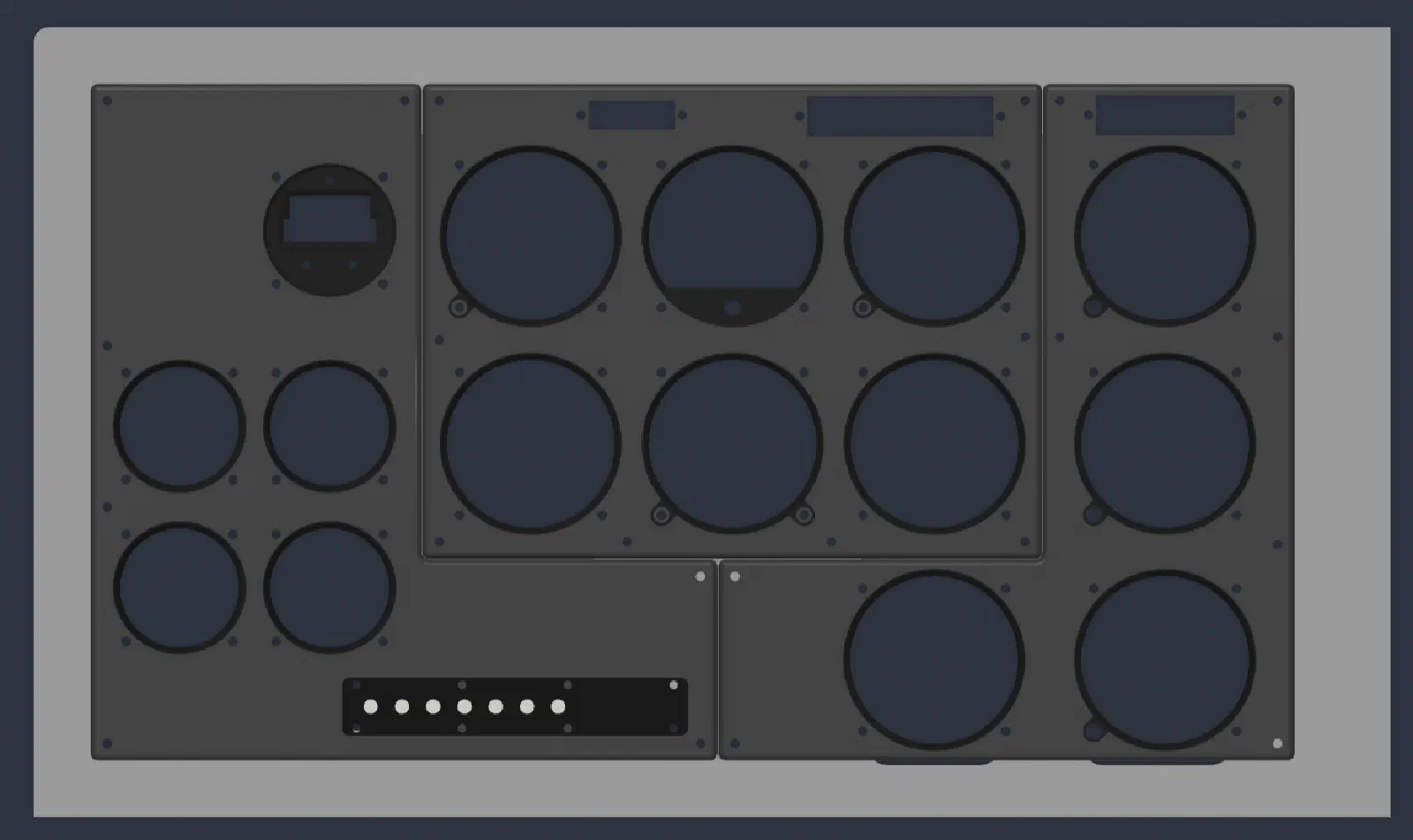
The openings need to align with the instruments on the screen.
The spacing needs to look right.
The panel needs to sit close enough to the monitor that the instruments don’t look disconnected from the physical controls.
And the controls need to be positioned so that they correspond to what I’m seeing on the display.
This is where the project starts becoming more of a mechanical design problem than a software problem.
Designing Around a Flat Display
One of the advantages of using a monitor is flexibility.
I can change the graphics without changing the physical hardware.
But that flexibility comes with a tradeoff.
The screen has a fixed physical size and aspect ratio, while the aircraft panel was designed around physical instruments.
I therefore need to design the overlay around the monitor rather than simply designing an aircraft panel and putting a monitor behind it.
That means accounting for:
- Screen dimensions
- Instrument diameter
- Primary instrument spacing
- Secondary instrument locations
- Viewing angle
- Monitor bezel
- Panel thickness
- Knob clearance
- Button placement
- Mounting points
- Access for maintenance
Even small differences become noticeable when the physical controls are sitting directly over the graphics.
The physical overlay aligned with the simulated C172 instrument panel.
Adding Physical Controls
The next step is adding physical controls to the instruments.
This is where the prototype starts to become more interesting.
The goal isn’t to add a generic collection of buttons and encoders somewhere on the panel. The controls should correspond to the instruments they operate.
For example, the altimeter needs a physical control for adjusting the barometric setting, while the heading indicator needs a heading adjustment.
The secondary instruments may have their own controls or interfaces depending on how they are represented in the X-Plane panel.
The important part isn’t simply adding inputs to the simulator.
It’s putting those inputs where they belong.
If I reach for the altimeter, I should be reaching for the altimeter.
If I adjust the heading, my hand should move to the heading indicator.
That physical relationship between the control and the instrument is an important part of the design.
Prototyping Before Designing Custom Electronics
I’m deliberately not designing the final electronics yet.
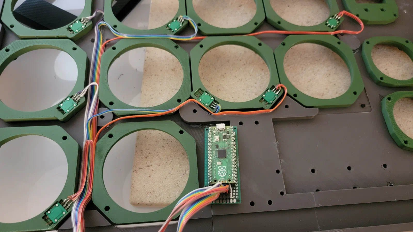
The Raspberry Pi and readily available components give me a convenient platform for getting the prototype working without committing to a custom PCB.
At this stage, I don’t know enough about the final panel to justify designing the electronics around it.
The physical design will probably change several times.
A knob may need to move.
An instrument opening may need to change size.
A control may need a different type of encoder.
The spacing might need adjustment.
All of those changes are much easier to make while working with a prototype.
Once the physical design stabilizes, the project can move toward custom electronics and purpose-built PCBs.
Prototype electronics used to test the physical controls.
Why Prototype This Way?
There is a temptation with a project like this to jump immediately into custom hardware.
As an embedded software engineer, designing the electronics and writing the firmware is arguably one of the more familiar parts of the problem.
But that isn’t necessarily the part that needs to be solved first.
The bigger unknown is the human interface.
What size should the controls be?
How much spacing is needed?
What does the panel look like when viewed from the normal pilot position?
Do the controls feel natural?
Can I operate them without consciously thinking about where they are?
Those are questions that a PCB can’t answer.
A quick prototype can.
The Physical Interface Is the Product
The more I work on this project, the more I think about the simulator as a combination of several different systems.
There is the simulation software.
There is the display system.
There is the electronics.
And then there is the physical interface between the pilot and the simulator.
That last part is easy to overlook.
A high-resolution monitor can produce a very convincing instrument display, but if interacting with it feels like operating a computer rather than an aircraft, some of that realism disappears.
The overlay is an attempt to solve that problem.
The monitor handles the things that are difficult to reproduce physically—the moving needles, attitude display, numbers, engine indications, and other graphical elements.
The physical panel handles the things that benefit from tactile feedback.
It’s a hybrid approach.
What’s Next?
The six-pack is an intentionally manageable first step, but the prototype already includes the surrounding secondary instruments.
That gives me a better representation of the complete C172 instrument panel and lets me evaluate the physical overlay as a whole rather than designing around only the six primary flight instruments.
Once the basic concept is working, I can start refining the mechanical design and determining which parts should become custom hardware.
The eventual goal is to move from a prototype built from readily available components toward a purpose-built panel with custom PCBs and electronics.
But before getting there, I want to spend some time using the prototype.
That’s an important part of the engineering process for this project.
Build it. Use it. Find the problems. Then redesign it.
The six-pack and secondary instruments give me a manageable first step toward testing that process.
And if the physical overlay works as intended, the same approach can be extended to the rest of the C172 cockpit.
Complete C172 instrument panel prototype installed in the simulator.
Project Status
Current stage: Prototype
Simulation: X-Plane 12
Instrument software: Air Manager
Prototype platform: Raspberry Pi
Panel: C172 six-pack and secondary instruments
Physical interface: Custom instrument panel overlay
Next stage: Refine the mechanical design and begin developing custom electronics
The ultimate goal isn’t simply to build a panel that looks like a Cessna 172.
It’s to build one that operates like one and feels familiar to use.