Aviation Moving Map
Project Inspiration
This project grew out of a couple of interesting projects I came across on YouTube.
The first was Offline Map Viewer with ESP32 and Round Display. The combination of an ESP32, a round display, and offline map data immediately caught my attention. It provided the inspiration for exploring what I could do with the ESP32-P4 and its 800 × 800 round touchscreen.
The second was A Real Mini Map from Need for Speed. This project demonstrated a very different application of a small map display, but the idea of having a compact, dedicated map that dynamically represents position was particularly interesting.
I decided to take those ideas in an aviation direction.
Rather than simply reproduce either project, I wanted to build something that combined the concepts with my own interests in aviation, embedded software, and electronics. I also wanted the project to be an opportunity to learn more about the latest capabilities of LVGL on the ESP32-P4.
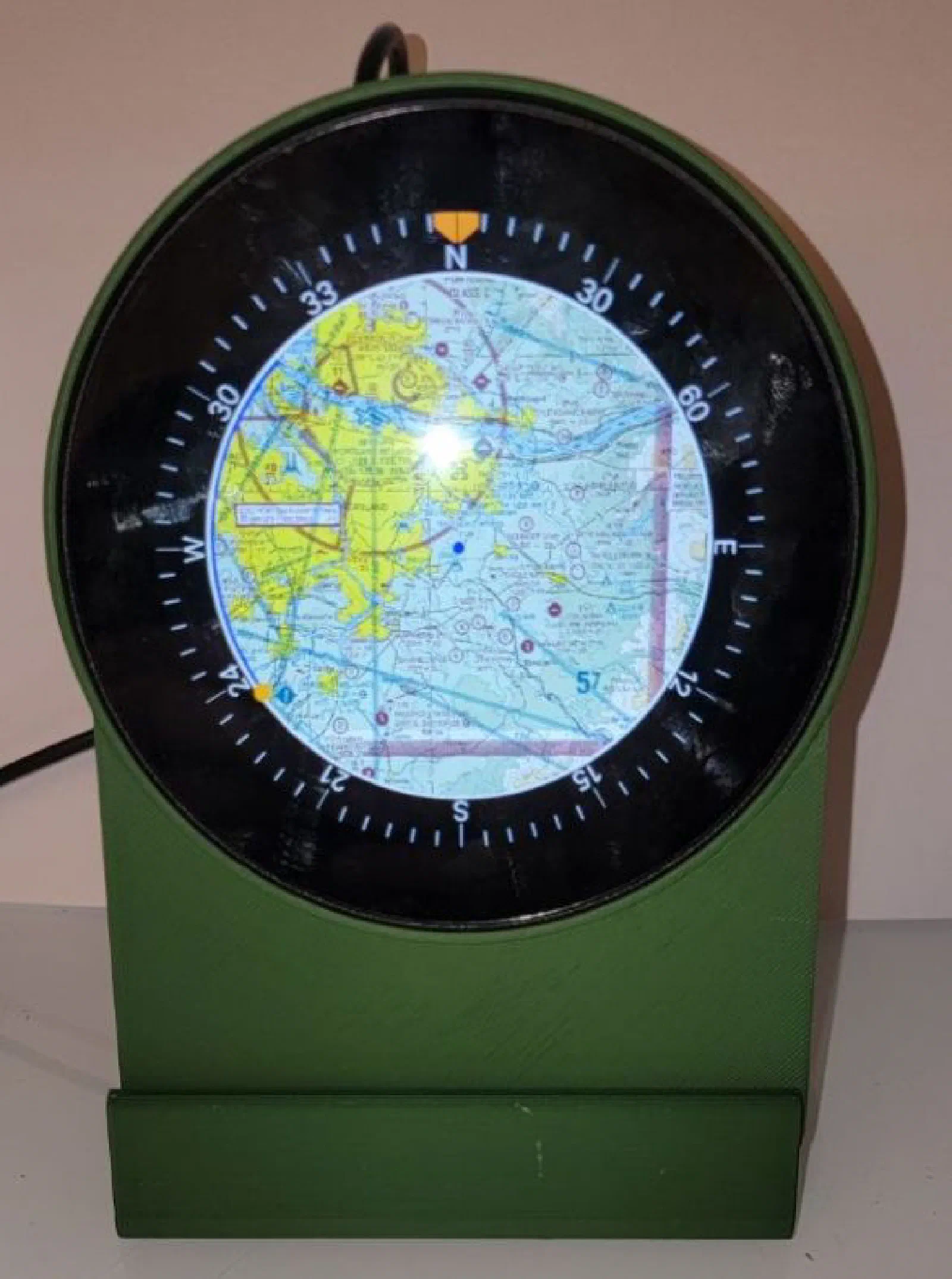
The result became an aviation-themed moving-map display using a NEO-6M GPS receiver, aviation map tiles generated with QGIS and QuickMapServices, and an 800 × 800 round touchscreen.
The Development Process
I deliberately approached the project in stages. Each stage provided a working milestone before adding the next piece of functionality.
1. Getting the Display and Touch Working
The first step was getting familiar with the development board itself.
Before worrying about GPS or maps, I wanted to make sure I understood the display hardware and could reliably communicate with the touchscreen through LVGL.
The initial goal was simple:
Get something on the screen and detect touch input.
This gave me a working foundation for experimenting with LVGL and learning how the display, touch controller, and graphics library fit together.
Once that was working, I had a platform on which I could build the rest of the project.
2. Creating the Aviation Map
The next challenge was the map.
I didn’t want to draw a simple background image and call it a map. I wanted to experiment with using actual map data and have the display behave more like a navigation display.
This turned out to be one of the more interesting parts of the project.
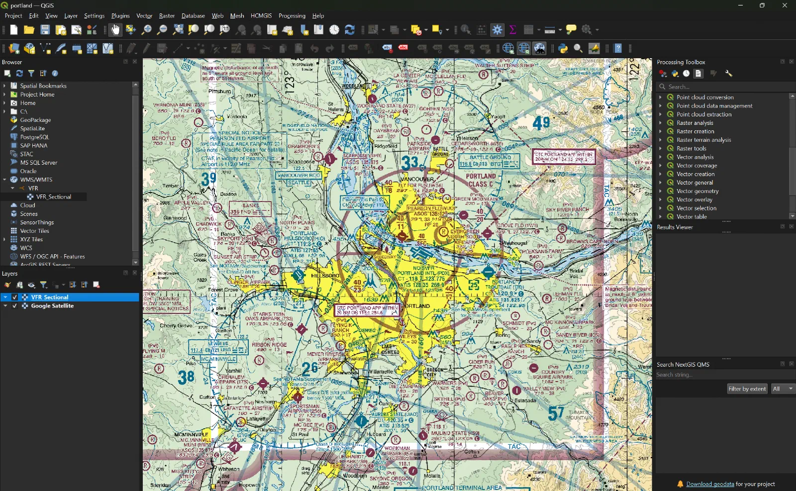
I used QGIS along with the NextGIS QuickMapServices plugin to work with the map data. QuickMapServices allows map and geospatial services to be added to QGIS, giving me a convenient starting point for creating the map imagery I needed.
QGIS gave me a convenient way to select the area I wanted, work with the map layers, and generate the tiles that would eventually be used by the embedded display.
The basic workflow was:
Map data
   ↓
QGIS + QuickMapServices
   ↓
Generate / organize map tiles
   ↓
SD Card
   ↓
ESP32-P4
   ↓
LVGL display
Depending on the Zoom Levels and area selected the generated map tiles can take several 10 Mbs. This far exceeds the ESP32-P4’s internal memory. Placing the map tiles onto an SD card provides considerably more flexibility. I can change the map coverage or add additional areas without having to redesign the entire application around a different embedded image.
3. Loading the Maps from the SD Card
With the tiles created, the next step was getting them onto the hardware.
The map tiles were loaded onto an SD card, which the ESP32-P4 could access while the application was running.
This changed the project from simply displaying a static image into something much closer to a real embedded mapping application.
The application now had to figure out which map imagery was needed and render it on the display.
This also introduced a number of interesting embedded-software problems around file access, image loading, memory usage, and rendering performance.
Those are exactly the kinds of problems I was hoping to encounter while learning more about LVGL.
4. Establishing GPS Communication
Once the display and map were working independently, it was time to add the other half of the project: GPS.
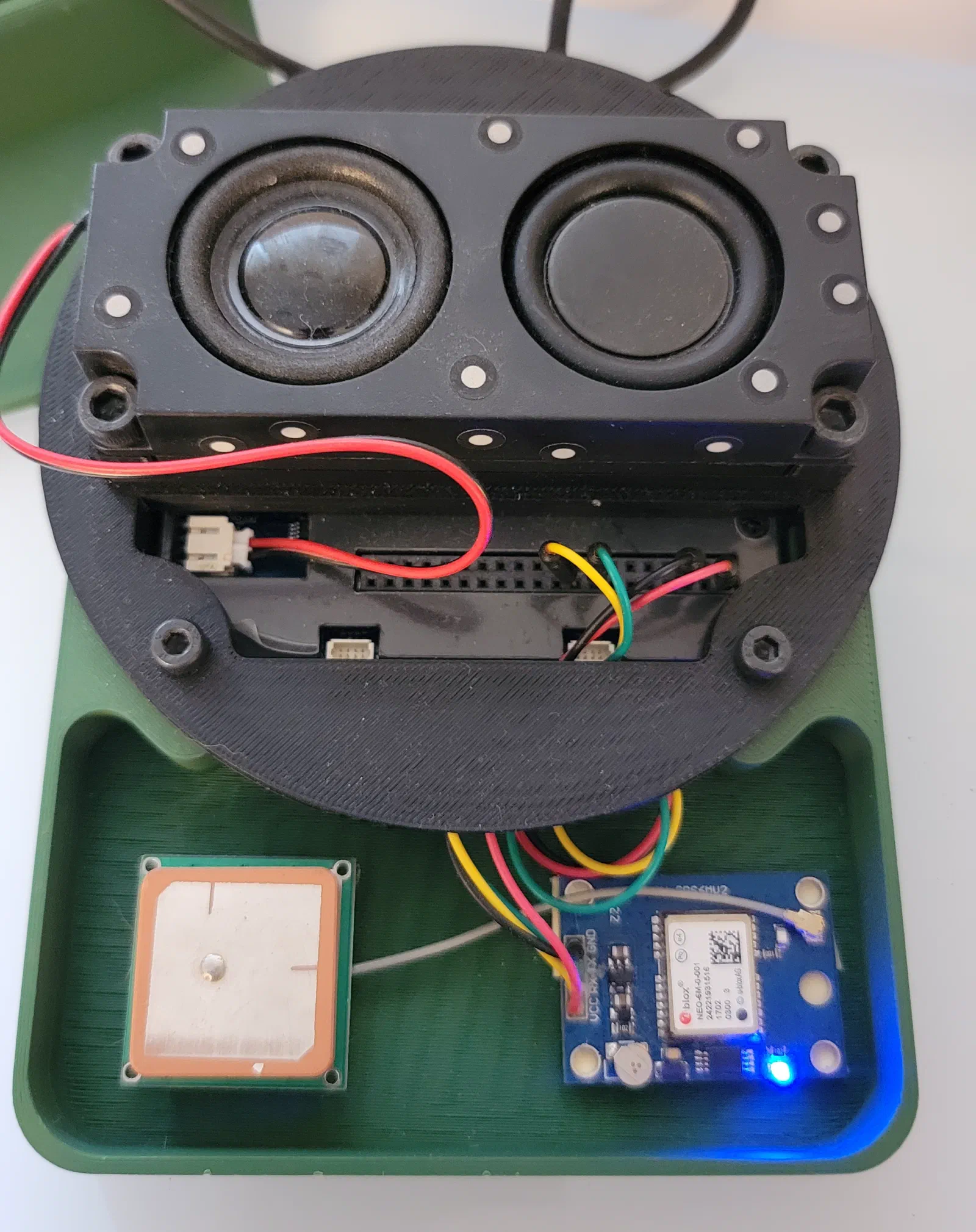
I connected a NEO-6M GPS module to the ESP32-P4 and established serial communication.
The GPS provides NMEA data containing information such as:
- Latitude
- Longitude
- Altitude
- Ground speed
- Track
- Fix information
- Satellite information
At this point the project could determine where the GPS receiver was located, but the position still needed to be connected to the map.
5. Putting the GPS Position on the Map
This was the point where the individual pieces finally started to come together.
The GPS provides a latitude and longitude. The map has its own coordinate system and tile layout. The application therefore needs to convert the GPS position into the appropriate location on the displayed map.
Once that was working, I could show a blue dot at the calculated position.
And then came the satisfying part:
It Moved.
As the GPS position changes, the application updates the position on the display.
At that point, it stopped feeling like a collection of separate experiments and started feeling like an actual instrument.
What’s Next?
The fun part of projects like this is that getting the first version working usually creates more ideas than it answers.
Obviously, this prototype is not an aviation-certified navigation device, and the maps and GPS data are being used for experimentation and development.
But as a platform for learning and building?
It’s pretty cool.
And I think there are plenty more instruments I can build from here.
Check out the code on GitHub.