Flap Control Module
Christopher Edwards
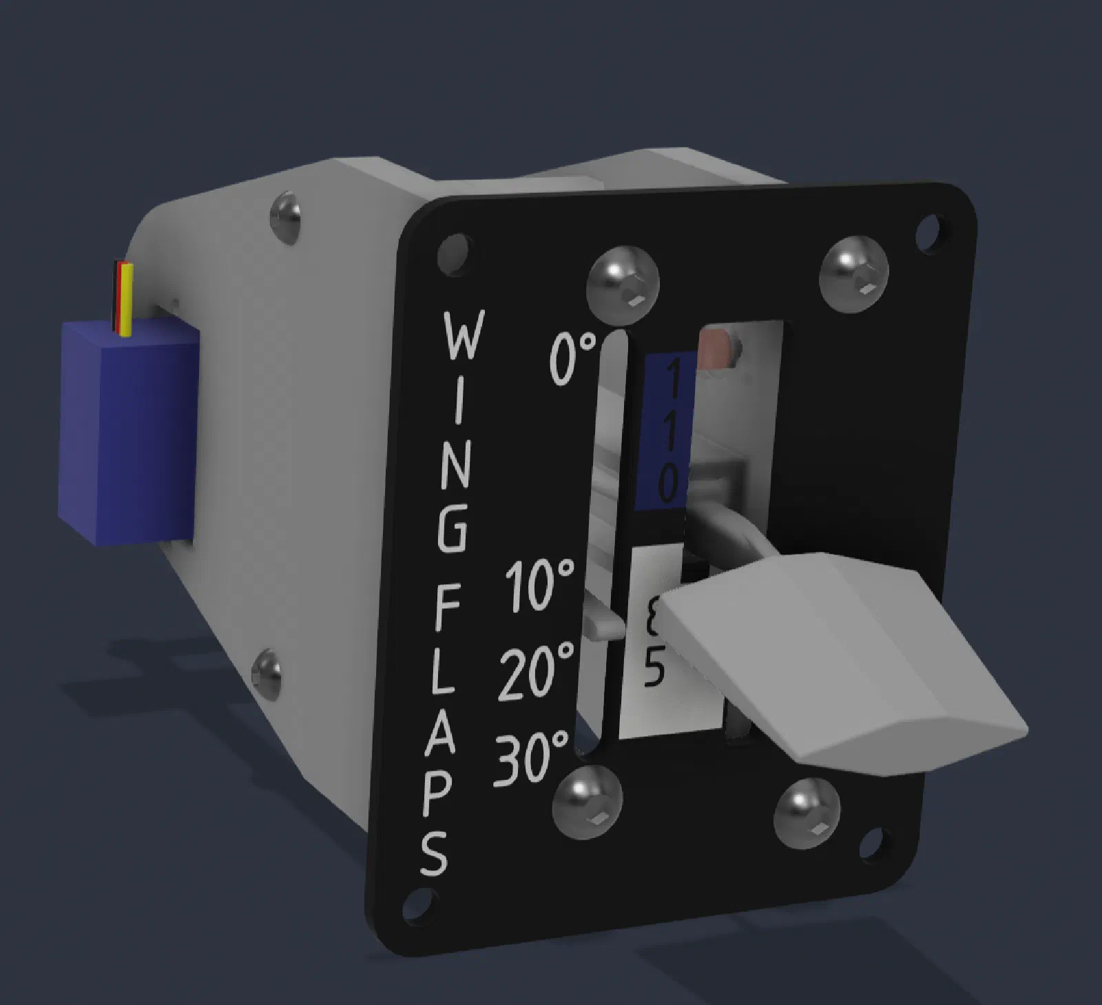
Designing the Flap Control: Integrated Position Sensing and Mechanical Detents
The flap control was another opportunity to approach the simulator hardware from first principles rather than simply reproducing an existing design.
Most of the flap controls I had seen for flight simulators use a fairly conventional approach: a lever moves through a set of positions, while the position is detected using a rotary encoder, potentiometer, microswitches, or similar electronic component.
For this design, I wanted to try something different.
The goal was to create a control that combined mechanical position feedback, electrical position sensing, and the physical feel of an aircraft flap control into one mechanism.
Starting From the Aircraft Interface
The Cessna 172 flap control is more than just a switch with several positions. The lever has defined positions corresponding to the available flap settings, with a mechanical interface that provides feedback as the lever is moved.
That physical feedback is important in a simulator. The control should not only send the correct electrical command to the simulator; it should also provide a physical interaction that resembles the aircraft control.
That led to two primary requirements:
- The control needed to reliably determine which flap position had been selected.
- The lever needed to provide a physical detent at each position.
Rather than treating these as two separate problems, I looked for a way to make them part of the same mechanism.
The Basic Concept
The design uses a sliding arm that travels along a surface containing a series of electrical contacts.
Instead of mounting a separate sensor to determine the lever position, the travel path itself becomes the position-sensing interface.
The arm carries a conductive wiper. As the lever moves, the wiper travels across the contact surface and bridges the contacts associated with each flap position.
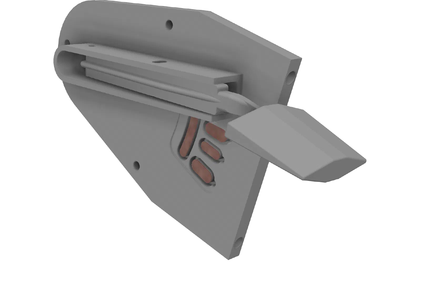
Conceptually, the mechanism works like a sliding switch:
Lever position → wiper location → electrical contacts → detected flap position
This keeps the electrical sensing directly tied to the mechanical position of the control.
Prototyping the Contact Surface
For the initial prototype, I didn’t want to immediately design and manufacture a PCB just to determine whether the sensing concept would work.
Instead, I used copper conductive tape to create the fixed contacts on the prototype surface.
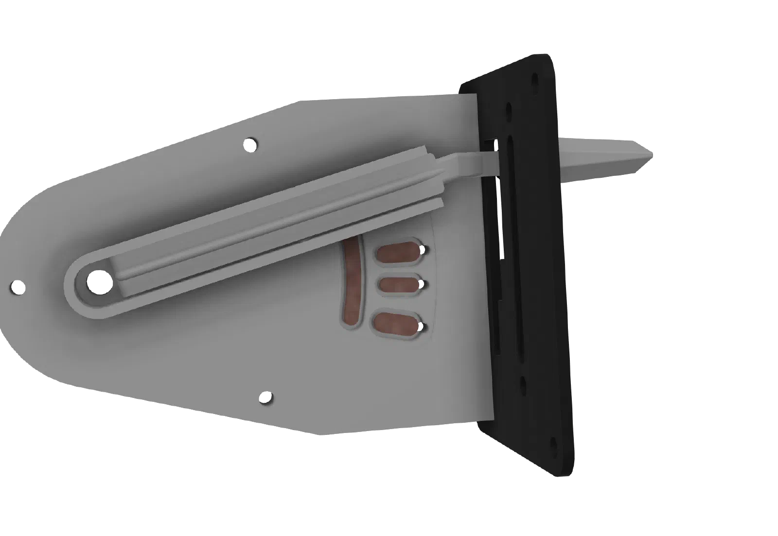
This provided a quick and inexpensive way to experiment with the contact layout and spacing. The contact pattern could be modified without redesigning a PCB, making it useful for validating the basic concept and adjusting the geometry.
The arm carried the corresponding conductive wiper. As the arm moved through its range, the wiper bridged the copper contacts and provided an electrical indication of the lever’s position.
The copper tape was therefore a prototype implementation, not intended as the final electrical interface.
Adding Mechanical Detents
The electrical contacts solve the position-sensing problem, but they don’t provide the physical feel I wanted.
The real control has distinct positions rather than feeling like a completely free-moving lever. I wanted the simulator control to provide similar tactile feedback.
The solution was to give the arm a small amount of lateral movement in addition to its primary travel.

The arm can move slightly sideways as it travels along the contact surface. This allows part of the mechanism to engage physical detents corresponding to the flap positions.
The result is a two-axis mechanical behavior:
- Primary movement: moves the lever between flap positions.
- Lateral movement: allows the lever to engage and disengage the detent features.
This allows the control to provide a more deliberate mechanical feel while still using the same arm for electrical position sensing.
Why Use Lateral Movement?
A conventional detent mechanism could have been added directly to the lever, but I wanted to explore whether the same arm used for electrical sensing could also interact with the mechanical detent system.
The lateral movement provides a simple way to do this.
As the lever is moved toward the next flap position, the arm can move laterally to clear the current detent. Once the lever reaches the next position, the mechanism returns toward the detent feature.
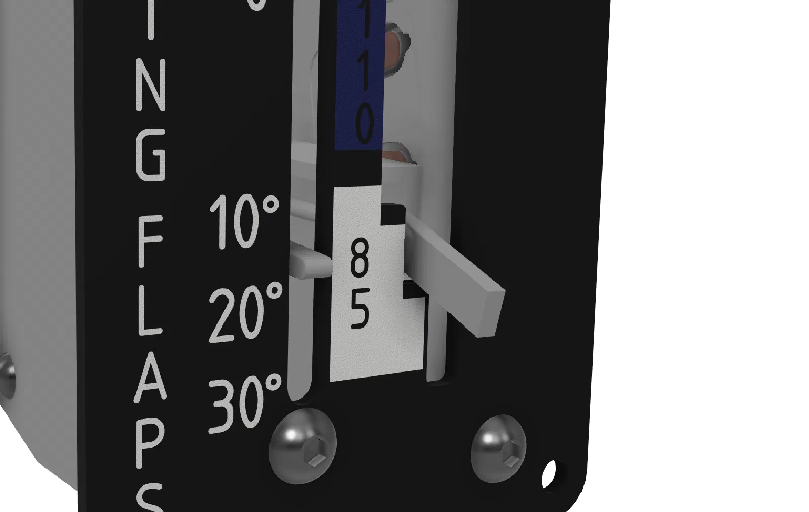
This creates a more deliberate interaction than simply adding friction to the lever.
Designing From First Principles
Starting with the desired physical behavior allowed the mechanical and electrical systems to be developed together.
The requirements can be reduced to a few basic relationships.
Mechanical position
The lever needs a set of repeatable positions.
Electrical position
Each mechanical position needs to produce a unique and reliable electrical state.
Tactile feedback
Moving between positions needs to require a deliberate action and provide feedback when the new position is reached.
Repeatability
The electrical contacts and mechanical detents need to remain aligned through repeated operation.
From those requirements, the architecture becomes:
Lever → Arm → Contact Surface
with the same arm providing both:
Wiper → Electrical position sensing
and
Detent interface → Mechanical position feedback
Prototype Construction
The first prototype was primarily intended to validate the mechanism.
Rather than spending time designing the final electrical hardware before knowing whether the concept would work, I used readily available materials to test the basic design.
The copper conductive tape provided the contact surface, while the 3D-printed mechanism established the lever travel, wiper movement, and lateral detent action.
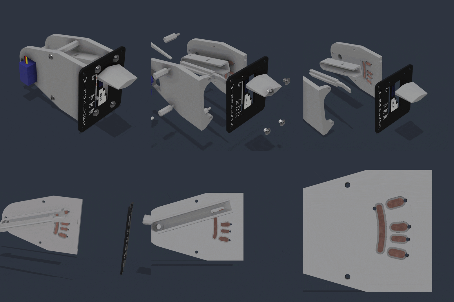
This allowed several questions to be answered early:
- Would the wiper maintain reliable electrical contact?
- Could the contact pattern distinguish the required positions?
- Could the arm move laterally without interfering with its primary travel?
- Would the detents provide the desired mechanical feedback?
- Could the mechanical and electrical systems coexist without making the lever difficult to operate?
The prototype demonstrated that the basic approach was viable.
Moving From Prototype to PCB
With the contact concept validated, the next iteration can address one of the obvious limitations of the prototype: the copper tape.
The next version will replace the taped contact surface with a custom PCB containing the fixed electrical contacts.
A PCB provides much better control over the contact geometry and spacing. It also makes the contact surface a repeatable manufactured component rather than something assembled manually from conductive tape.
The PCB can be designed around the final mechanical geometry, allowing the contact pattern, mounting points, and electrical connections to become part of the same component.
This is a good example of how I am approaching the hardware development for the simulator:
Prototype quickly → validate the concept → replace temporary techniques with purpose-built hardware.
The copper tape served its purpose by allowing the mechanism to be tested without committing to a PCB design too early. Now that the concept has been demonstrated, the PCB becomes worthwhile as the next engineering iteration.
What Worked
The integrated approach provided several benefits.
The biggest was the direct relationship between the physical control and its electrical output. The same movement that places the lever in a flap position also places the wiper over the corresponding electrical contacts.
The lateral movement also provided a way to reproduce the mechanical behavior of the aircraft control without requiring a separate sensing mechanism and a separate detent interface.
Most importantly, the design treats the flap control as a mechanical control first and an electronic input second.
The objective is not simply to make something that sends the correct command to X-Plane. The physical interaction should also reinforce the workflow and muscle memory associated with operating the aircraft.
Lessons Learned
The prototype reinforced the value of starting with the mechanical requirements before selecting the final electronic implementation.
It would have been easy to begin with a potentiometer, encoder, or collection of switches and then build a lever around it. Instead, defining the desired mechanical behavior first led to a different solution.
Using copper conductive tape also proved useful as a prototyping technique. It allowed the electrical contact layout to be tested and changed without requiring a new PCB for every mechanical revision.
Now that the concept has been validated, however, the limitations of the prototype implementation become more apparent. Contact geometry, wiper pressure, wear, alignment, and repeatability all become important considerations for the final design.
Next Steps
The next iteration will focus on turning the proof-of-concept into a more robust mechanism.
The primary change will be replacing the copper tape contacts with a purpose-designed PCB.
Additional areas for refinement include:
- Finalizing the PCB contact geometry.
- Refining the wiper design and contact pressure.
- Improving the detent shape and force.
- Improving alignment between the wiper and PCB.
- Evaluating contact wear over repeated operation.
- Making the mechanism easier to assemble and service.
- Refining the external lever and mounting hardware to better match the aircraft control.
The first prototype established that the core concept works: a single arm can provide both electrical position sensing and mechanical detent feedback.
The next iteration moves the design from a quick prototype using copper conductive tape toward a purpose-built PCB that can serve as the permanent contact surface.