Fuel Selector
Christopher Edwards
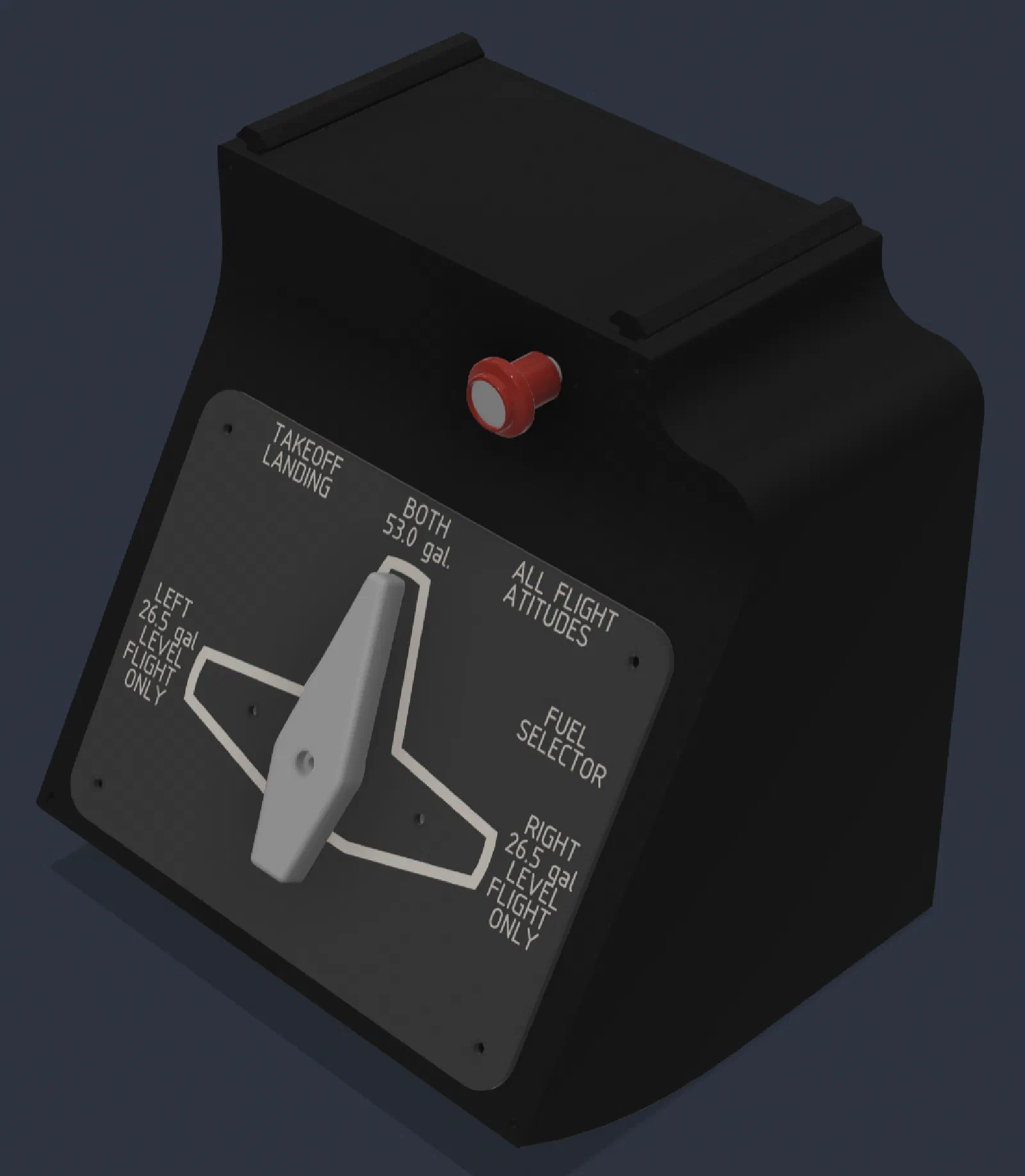
Building the Fuel Selector: Cam-Driven Detent Mechanism
The fuel selector was another opportunity to build a cockpit control from scratch rather than adapting an off-the-shelf component. The goal was to create a selector with three distinct positions, a positive mechanical click between positions, and a simple electrical interface.
The solution ended up being intentionally simple: three limit switches actuated by a custom cam with integrated detents.

Initial Concept
I wanted the fuel selector to have a definite mechanical feel. A smooth rotary control would work electrically, but it would not provide the same confidence when moving between positions.
At the same time, I didn’t want to build a complicated rotary switch mechanism just to get three discrete inputs.
The initial concept was therefore based on separating the two requirements:
- Use a cam and detents to create the mechanical feel.
- Use three limit switches to determine the electrical position.
This keeps the design relatively compact and uses simple, inexpensive components.

The selector shaft rotates the cam as the knob is turned. The cam profile determines when each limit switch is actuated, while the detent geometry provides the physical feedback for each position.
Prototype
The first prototype focused on validating the basic mechanical concept rather than producing a finished cockpit component.
A custom cam was designed with three defined positions. The three limit switches were positioned around the cam so that the cam could actuate the appropriate switch as the selector rotated.
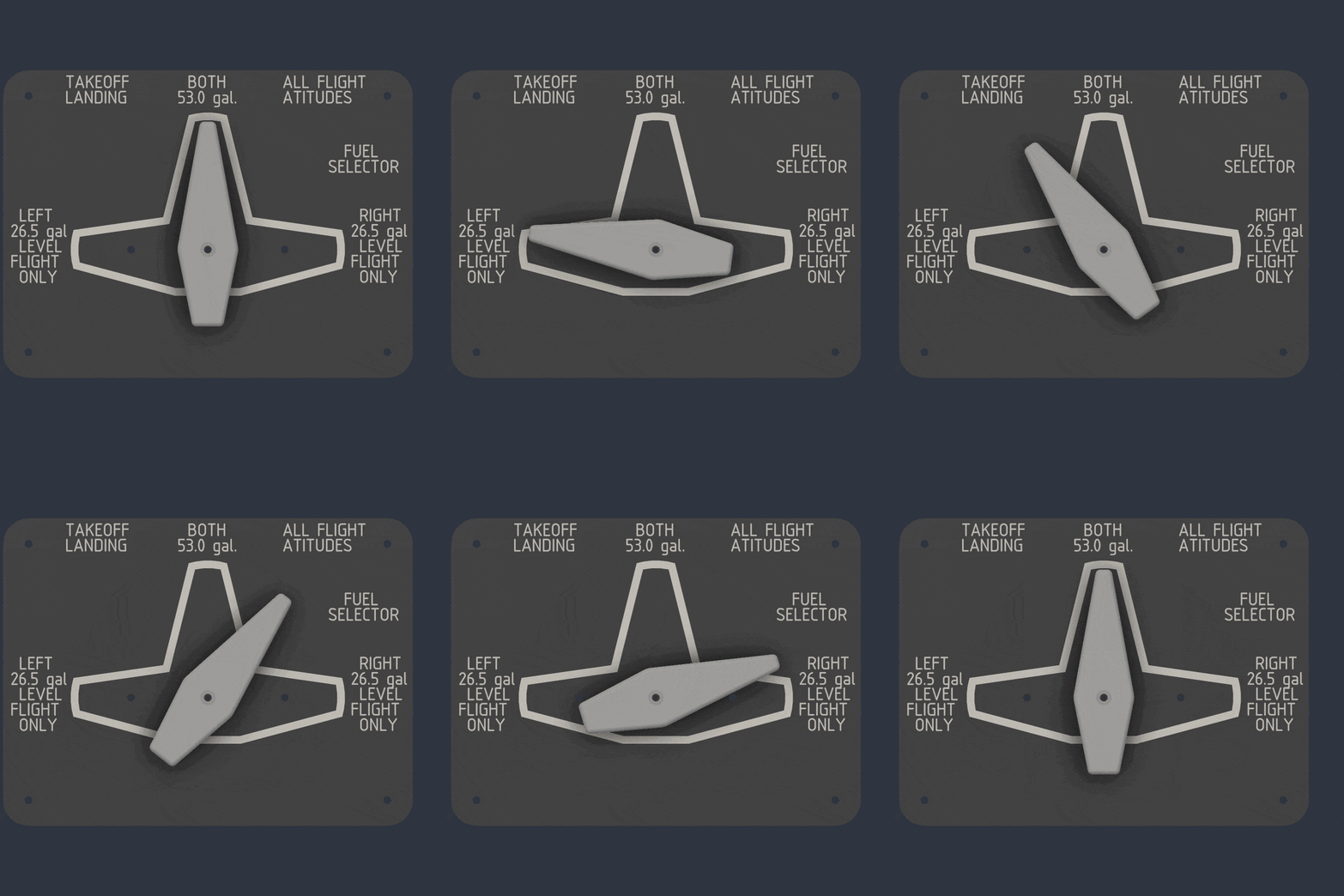
The important part of the prototype was the relationship between the cam and the switches. There needed to be enough switch travel to reliably actuate each switch without requiring excessive rotation or force at the knob.
The detents were incorporated directly into the cam rather than adding a separate spring-and-ball detent mechanism.
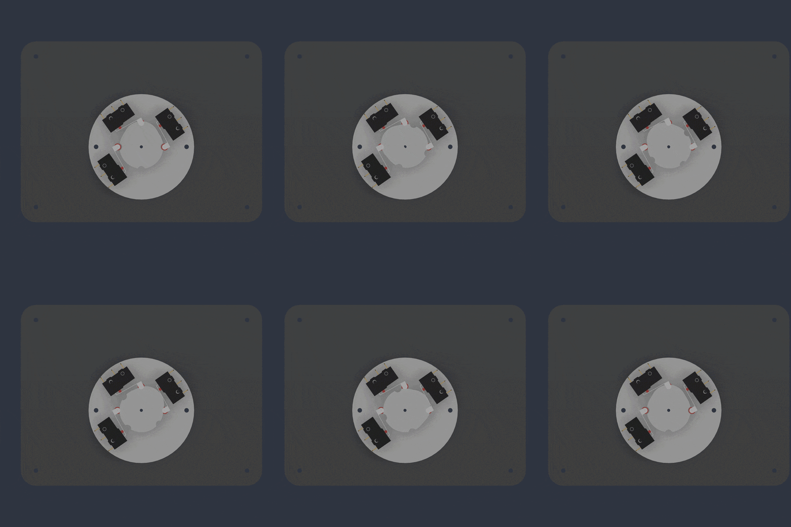
This reduced the number of components and kept the mechanism straightforward.
Testing
With the prototype assembled, testing focused on both the mechanical feel and electrical position detection.
Mechanical Testing
The first test was simply rotating the selector through its full range.
The detents needed to provide a clear transition between positions without making the selector excessively difficult to turn. The selector should also naturally settle into each position rather than stopping somewhere between them.
The cam-based approach worked well for this because the same geometry that controlled the switches could also establish the three mechanical positions.
Switch Testing
The second part of testing was verifying that each position produced a reliable electrical state.
Each limit switch corresponds to one selector position, giving the controller three discrete inputs.
This was much simpler than trying to determine the selector position from an analog signal. The controller only needs to identify which switch is active.
Testing also provided a straightforward way to troubleshoot the mechanism. If a position was not being detected, the problem could be isolated to the switch, wiring, cam alignment, or mechanical travel.
Refinements
Once the basic mechanism was working, the focus shifted to refining the cam geometry.
The cam controls several things simultaneously:
- Position of the selector.
- Limit-switch actuation.
- Detent depth.
- Rotation required between positions.
- Overall feel of the control.
This made the cam an important part of the overall design. Small changes to the profile could change both the switch travel and the tactile feel of the selector.
Rather than adding more mechanical components to solve individual problems, the approach was to refine the cam itself.
The three-switch arrangement also kept the electrical side simple. There was no need for a complicated rotary contact assembly or additional electronics to determine the selector position.
Final Design
The final design uses a custom cam, three limit switches, and the selector shaft and knob to create the complete mechanism.
The cam provides the positive detents while simultaneously actuating the switches. Each selector position therefore has both a physical position and a corresponding electrical state.
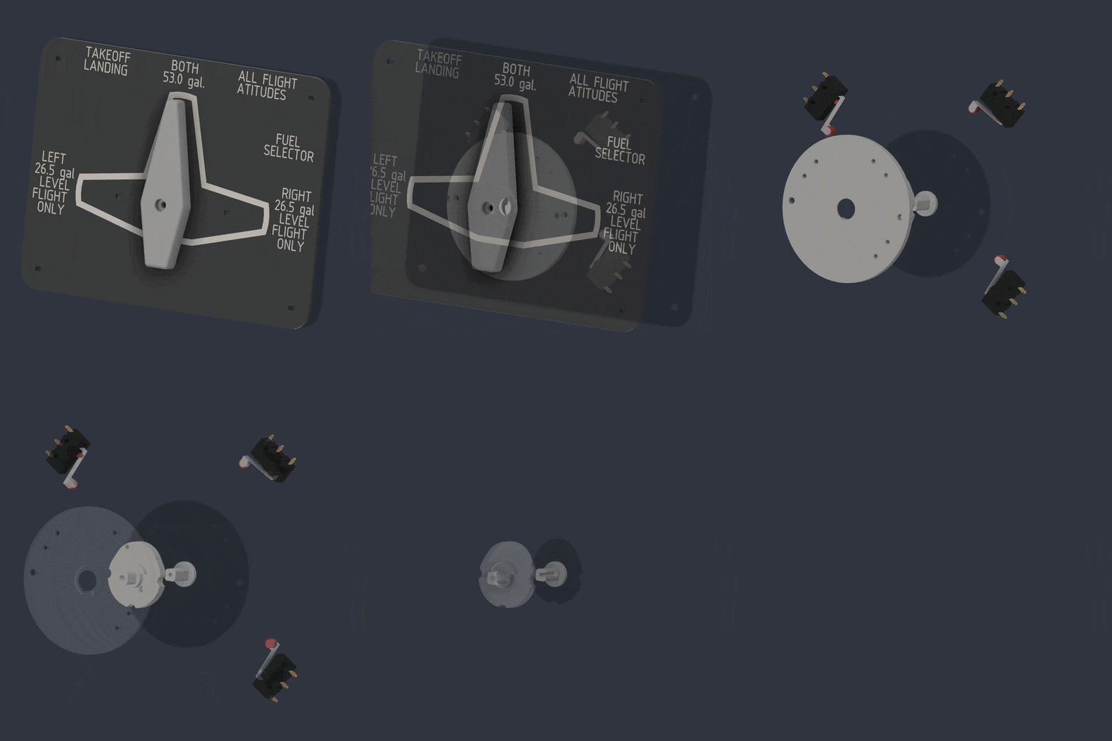
The design is intentionally low-part-count. Instead of using separate mechanisms for the detent and position sensing, the cam performs both functions.
From the controller’s perspective, the interface is equally simple: three digital inputs represent the three selector positions.
Result
The finished selector achieves the original goals without adding unnecessary complexity.
The three positions are mechanically defined by the cam, each position produces a positive click, and the limit switches provide direct position feedback to the simulator electronics.
The biggest advantage of the design is its simplicity. There are relatively few components, the mechanism is easy to understand, and the cam can be modified if the feel or switch actuation needs further adjustment.
Lessons Learned
This was another example where a relatively small amount of mechanical design can eliminate a lot of electronic complexity.
Rather than using a sophisticated rotary position sensor, the selector uses three simple switches. Rather than adding a separate detent mechanism, the cam incorporates the detents into its geometry.
The result is a control that is mechanically simple but still provides the tactile feedback expected from a cockpit control.
For this type of simulator hardware, a carefully designed mechanical interface can often do more with fewer parts.