Making the G5 Panel
Christopher Edwards
1st Iteration of the G5 Panel.
C172 Panel Update: Dual G5s, Overlay Refinement, and Wiring
Project Journal — Febuary 2026 Project: Cessna 172 Flight Simulator Iteration: Main Panel Prototype Update
The first version of the panel was built to answer a fairly simple question: could I use a monitor, Air Manager, and a physical overlay to create a convincing Cessna 172 instrument panel?
The answer was yes.
Once that prototype was assembled, though, a few things became apparent. The six-pack layout was useful for proving the concept, but it didn’t represent the type of modernized training aircraft panel I wanted to build. The physical overlay also needed refinement, and the wiring behind the panel needed to be rearranged so everything would fit properly over the monitor.
This iteration is about addressing those issues.
Photo of the original C172 panel showing the six-pack configuration, monitor, and physical overlay.
Problem #1 — The Instrument Layout
The original prototype used a traditional six-pack arrangement based on the default C172 configuration in X-Plane 12.
That was a good starting point because it provided a familiar layout and made it easy to get the initial prototype working. As the project developed, however, I wanted the simulator to better reflect the equipment found in the training aircraft I am using as inspiration.
Modernized C172s can have very different avionics from the traditional six-pack configuration.
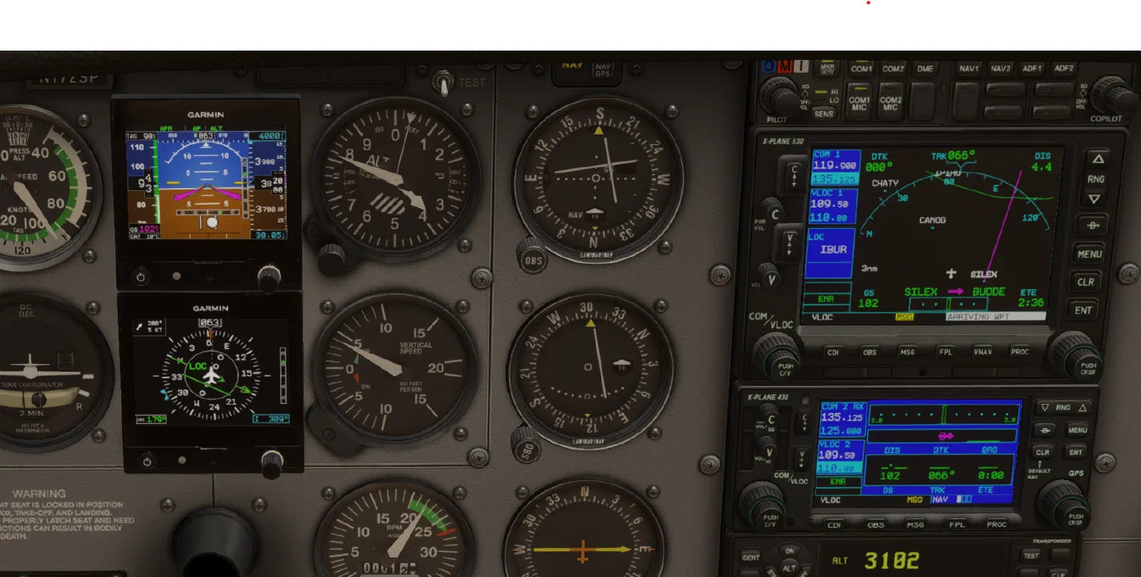
For this iteration, I decided to move to a dual G5 configuration for the primary flight instruments.
Change
The two primary instruments were changed to G5-style displays using Air Manager.
The rest of the panel continues to use the virtual instruments displayed on the monitor, while the physical overlay provides the aircraft-style interface around them.
This keeps the prototype relatively simple while allowing the physical panel to evolve independently from the display software.
Front view showing the updated dual-G5 instrument arrangement on the monitor.
Result
The panel now has a much closer relationship to the type of modern training aircraft configuration I want the simulator to represent.
It also gives the simulator a more useful foundation for practicing normal cockpit workflows rather than simply reproducing an older six-pack panel.
Lessons Learned
The first prototype did exactly what it needed to do: it helped establish what needed to change.
It is much easier to make these decisions after seeing the complete panel assembled than it is to try to determine everything from a CAD model.
Problem #2 — The Overlay Looked Too Much Like a Prototype
The original overlay was primarily functional.
The important part was getting the instrument openings in the right locations and providing a physical surface for the controls. Once the panel was assembled, however, it was clear that the overlay itself needed more attention.
A simulator can have convincing virtual instruments, but if the physical panel surrounding them looks unfinished, the whole cockpit still feels like a prototype.
Change
The overlay was refined around the new instrument configuration.
The focus was not just on making the holes line up with the monitor. I also wanted the panel to have better proportions and a more intentional aircraft-panel appearance.
This included looking at:
- Instrument spacing
- Instrument alignment
- Control placement
- Panel proportions
- Edges and openings
- Label placement
- The relationship between the physical overlay and the monitor
The objective was to make the overlay feel like part of the instrument panel rather than simply a piece of material placed in front of a screen.
Result
The updated overlay has a cleaner appearance and better integrates the physical controls with the virtual instruments.
There is still plenty of room for refinement, but the panel is beginning to look like a cockpit component rather than an electronics prototype.
Lessons Learned
The visual details matter more than expected.
Small differences in spacing and alignment become very noticeable when looking at the entire panel. Designing the overlay is therefore becoming an iterative process rather than something that can be finalized in one pass.
Problem #3 — The Wiring Didn’t Package Well
The original wiring was built around getting the prototype working.
That was the right priority for the first iteration, but once the complete panel was assembled, the physical packaging became a problem.
The wiring and connections behind the overlay needed to coexist with the monitor. There simply isn’t much space between the back of the panel and the monitor surface.
Some of the wiring was positioned in ways that made it harder for the panel to sit cleanly over the display.
Change
The wiring was rearranged specifically to improve the physical fit of the panel over the monitor.
Rather than treating the wiring as something separate from the mechanical design, I started routing it with the actual panel and monitor geometry in mind.
The goal was straightforward:
Make the wiring fit the panel instead of making the panel fit the wiring.
Connections were repositioned and wiring was routed to reduce interference behind the overlay.

Result
The panel now fits more cleanly over the monitor, with less interference from the wiring behind it.
This doesn’t represent the final electrical architecture. The current electronics are still primarily being used for prototyping.
The improvement is really about mechanical packaging.
As more physical controls are added, that packaging is going to become increasingly important.
Lessons Learned
Wiring is part of the mechanical design.
It is easy to think of wiring as something that happens after the hardware has been designed. In a compact simulator panel, that doesn’t work particularly well.
The wires have to occupy physical space, and that space needs to be accounted for from the beginning.
Putting the Changes Together
The interesting part of this iteration is that none of these changes are particularly large on their own.
The G5 displays are primarily a change to the virtual instrument configuration.
The overlay is a physical refinement.
The wiring changes are mostly about packaging.
Together, though, they make the panel feel substantially more cohesive.
This is also where the value of the prototype becomes apparent.
The first version wasn’t intended to be the final panel. It was a way to discover the problems that weren’t obvious on paper.
Now those problems can be addressed one at a time.
Lessons Learned From This Iteration
1. Build the prototype before committing to the final design
The physical prototype continues to expose problems that aren’t obvious in CAD.
2. Mechanical and electrical design are closely connected
The wiring may work electrically, but it still has to physically fit inside the available space.
3. The overlay is part of the user interface
It isn’t just a mounting plate. The shape, spacing, labels, and physical controls all contribute to how the simulator feels to operate.
4. Design around the aircraft, not just the simulator
The goal is to reproduce the interaction patterns of a training aircraft. The panel layout and controls should support the same kinds of cockpit workflows.
Next Iteration
With the dual-G5 configuration in place and the basic packaging cleaned up, the next step is to continue refining the physical panel.
The main areas I’m watching are:
- Final instrument and control spacing
- Overlay construction
- Switch and knob placement
- Wiring access and serviceability
- Physical mounting
- Integration with the rest of the simulator
The electronics will eventually move toward custom-designed hardware and PCBs, but there is still value in using the current prototype hardware while the physical design is changing.
For now, the process remains the same:
Build → test → find the problem → change the design → build again.
That’s really what this project is becoming—a flight simulator built one engineering iteration at a time.