GNS530 PCB
Christopher Edwards
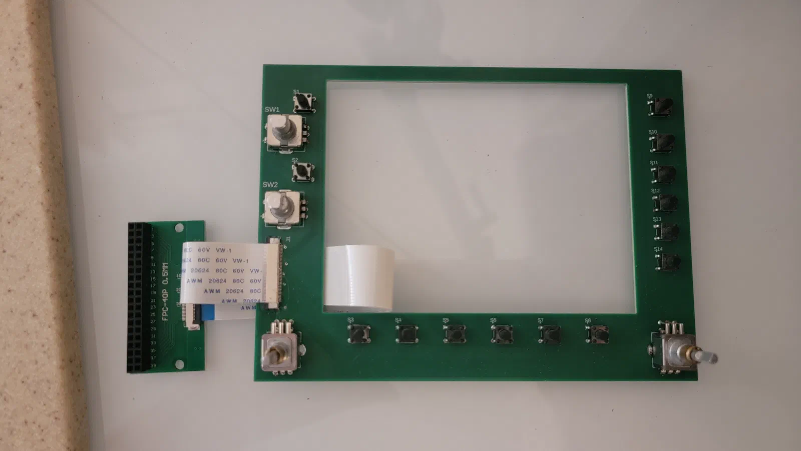
Building the GNS 530 Control PCB
The first GNS 530 prototype used a touchscreen and an Arduino Mega 2560 Pro Mini to provide the controls and interface. That approach was useful for getting the basic functionality working, but it didn’t provide the physical interaction of an actual avionics unit.
The next step was to move the controls onto a dedicated PCB that could become part of a physical GNS 530 overlay.
The larger goal is to develop a modular avionics stack where individual components can be swapped in and out while sharing a common display. The GNS 530 is the first step toward moving away from the touchscreen-based controls and toward physical, interchangeable avionics hardware.
Initial Concept
The basic idea was to separate the physical controls from the rest of the controller electronics.
The PCB would contain the buttons and rotary controls that make up the front panel of the GNS 530. Rather than placing the processor and all of the supporting electronics directly on the front-panel board, the PCB would connect through a ribbon cable to a separate breakout board.
This creates two useful layers:
- GNS 530 control PCB — physical buttons, knobs, and their associated wiring.
- Breakout/controller board — connection to the microcontroller and the rest of the simulator hardware.
This approach keeps the GNS 530 PCB focused on replicating the physical interface while keeping the electronics behind it flexible.
PCB Design
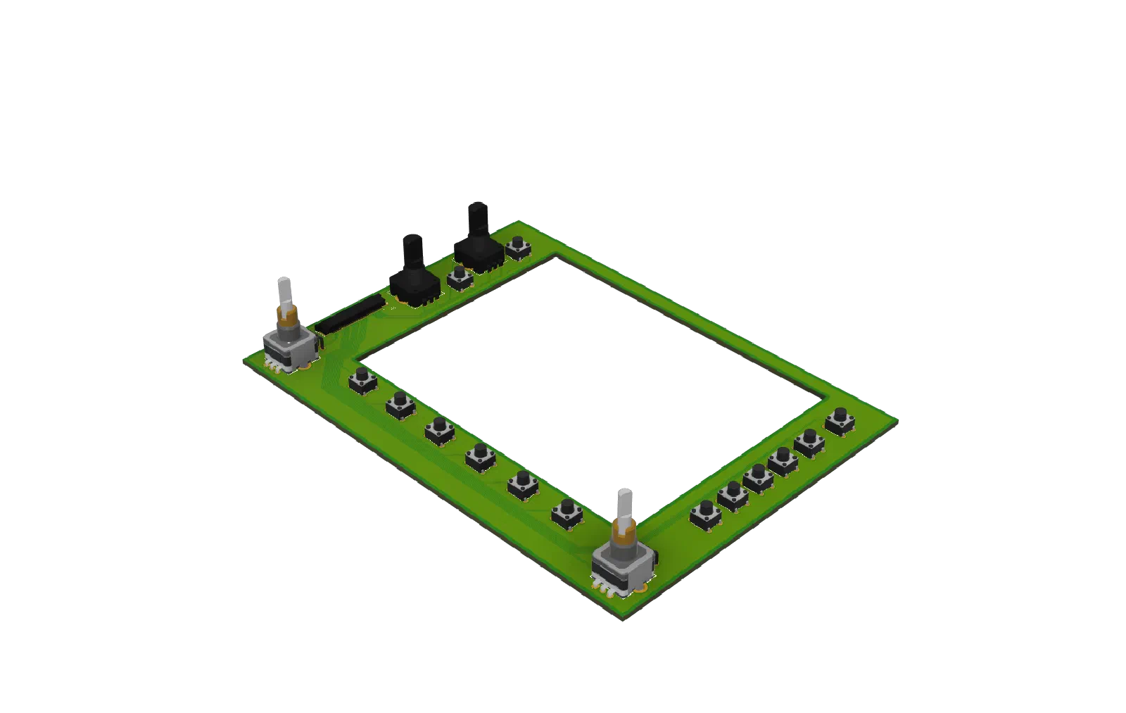
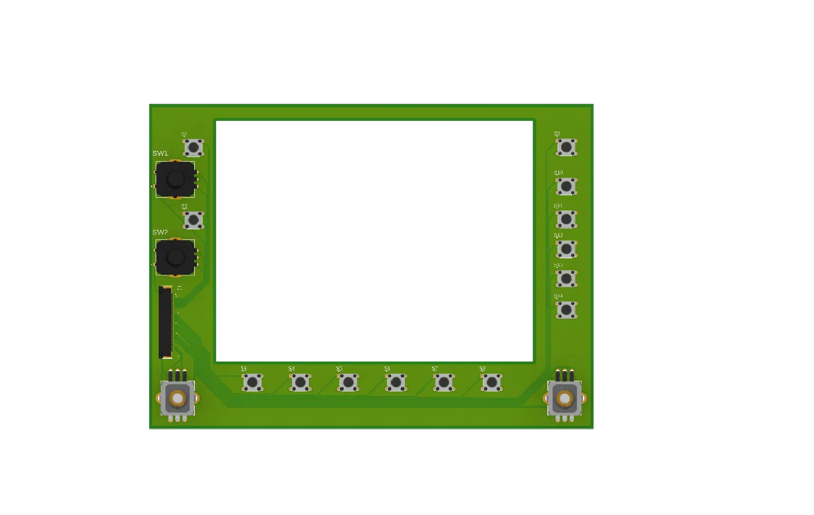
The PCB was laid out around the physical arrangement of the GNS 530 controls.
The goal wasn’t simply to replace a collection of switches with a circuit board. The board needed to become a structural part of the eventual avionics overlay, providing a consistent mounting location for the controls while keeping the overall assembly relatively compact.
The buttons and rotary encoders are mounted directly to the PCB, eliminating much of the point-to-point wiring that would otherwise be required behind the panel.
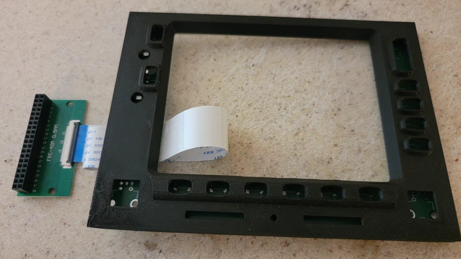
The resulting board becomes a single module that can be mounted behind an overlay containing the appropriate labeling and graphics.
Ribbon Cable Interface
Rather than connecting the PCB directly to the controller, I added a ribbon-cable interface.
The ribbon cable connects the GNS 530 PCB to a breakout board. This provides a convenient transition between the densely packed front-panel controls and the more general-purpose electronics used to interface the device with the simulator.
This also makes the PCB easier to reuse during development. The control board doesn’t have to be tied to one particular processor or controller implementation.
The breakout board can handle the connections to the existing hardware and provide a convenient place to experiment with different ways of interfacing the controls.
Prototype and Testing
With the PCB assembled, the next step was verifying that the physical controls could be integrated with the existing GNS 530 code.
The intent was to retain as much of the existing software as possible. The original touchscreen implementation had already established the basic control logic, so the new hardware should provide the same logical inputs without requiring the simulator interface to know whether the input came from a touchscreen or a physical control.
This provides a useful separation between the hardware interface and the simulator functionality.
Testing also provided an opportunity to verify the mechanical layout. Button spacing, encoder placement, and the overall dimensions of the board all become much more important once the controls are intended to be installed behind a physical overlay.
Moving Toward an Interchangeable Avionics Stack
The GNS 530 PCB is part of a larger change in the design of the simulator.
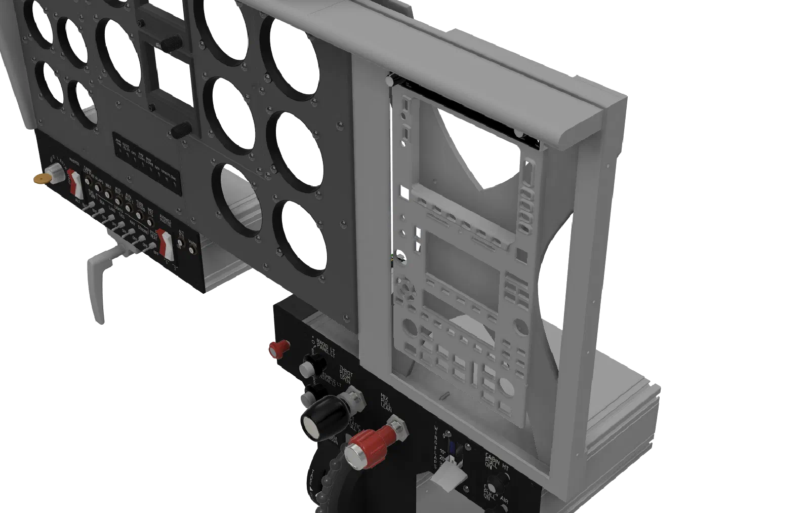
The eventual goal is to have interchangeable avionics components that can be installed as modules in a common stack. Each component would provide its own physical controls while using a shared display underneath the stack.
The display provides the visual interface, while the physical overlays provide the controls and appearance of the individual avionics units.
This makes it possible to experiment with different aircraft configurations without requiring a completely different simulator panel for every aircraft.
The GNS 530 is the first practical step toward that architecture.
Refinements
One of the advantages of using a separate breakout board is that the GNS 530 PCB doesn’t have to represent the final electronics architecture.
As the project develops, the controller hardware can change independently of the physical front panel. The same PCB can be used while experimenting with different microcontrollers, input-handling approaches, or simulator interfaces.
That flexibility is particularly useful while the avionics stack is still evolving.
The physical PCB also provides a much cleaner foundation for the eventual overlay than the original collection of touchscreen controls and prototype wiring.
Next Step
The GNS 530 control PCB establishes the basic pattern for future physical avionics modules: a dedicated PCB for the controls, a simple connection to the controller electronics, and an overlay that defines the appearance and mounting of the component.
The next step is to refine the mechanical integration between the PCB, overlay, and shared display.
Once that approach is established, the same concept can be applied to additional avionics components, gradually replacing the touchscreen interface with a stack of physical controls.