GNS 530 BreadBoard
Christopher Edwards
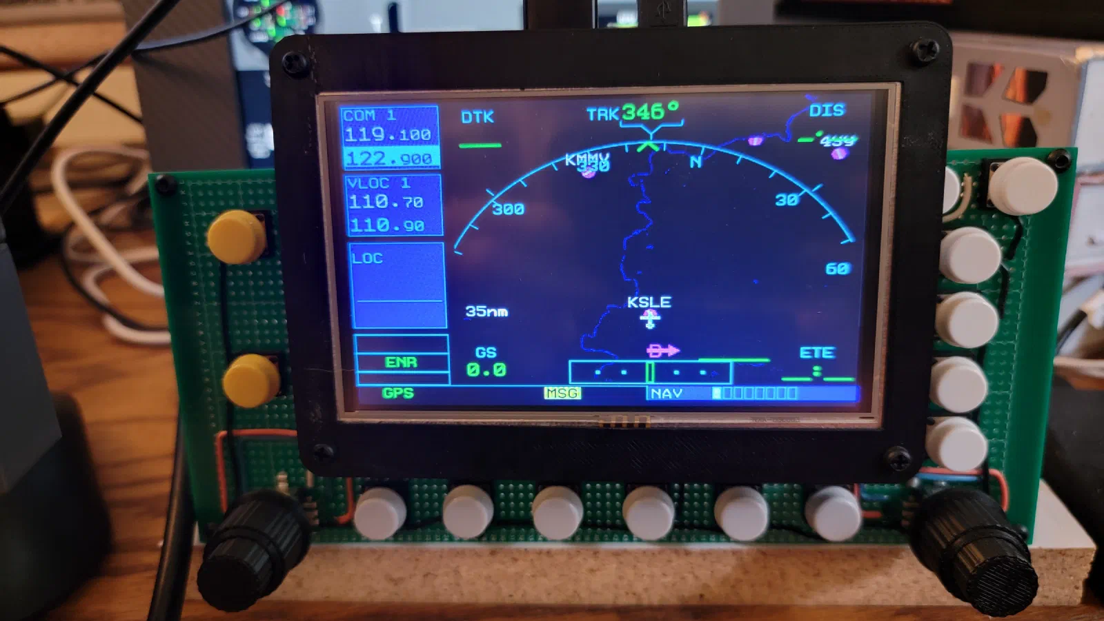
GNS 530 Prototype: First Steps on the Breadboard
Project: Cessna 172 Flight Simulator Component: Garmin GNS 530 Prototype: Mega 2560 Pro Mini + Air Manager Stage: Initial Electronics Prototype
Project Journal
The next step in building the simulator was moving beyond the physical panel and starting to experiment with the electronics behind the controls.
For this stage, I wanted to build an initial prototype of the Garmin GNS 530 using a Mega 2560 Pro Mini and Air Manager.
The goal wasn’t to build the final hardware.
Instead, this prototype is about answering some basic engineering questions:
- How should the controls be wired?
- How many inputs will the GNS 530 require?
- How should the different knobs and pushbuttons be handled?
- How well can the Arduino-based hardware interface with Air Manager?
- What limitations will become apparent before designing a custom PCB?
The breadboard provides a quick way to experiment with those questions without committing to a final circuit-board design.
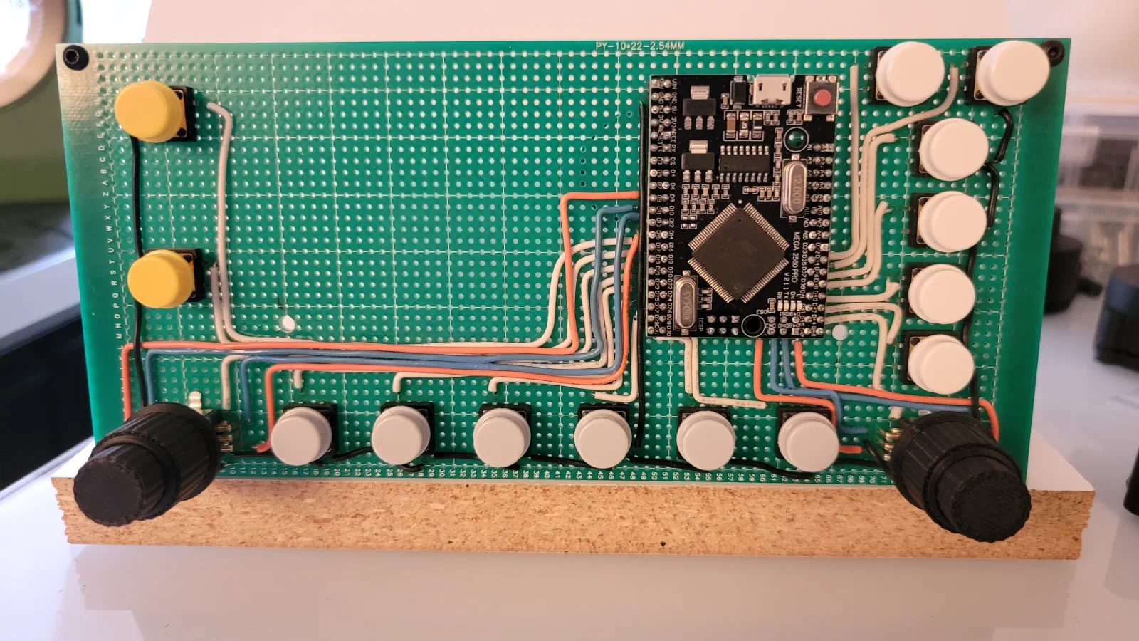
Starting Point
The physical GNS 530 is a fairly control-dense piece of equipment.
There are multiple rotary controls, pushbuttons, and dedicated controls that need to feel like separate physical inputs even though they ultimately have to be translated into commands for the simulator.
For the initial prototype, I chose the Mega 2560 Pro Mini because it provides a large number of digital I/O pins and is inexpensive and convenient for experimentation.
This makes it useful for determining what the final interface will actually require.
The Mega is not intended to be the final hardware platform. It is a prototyping tool.
That distinction is important for this project.
I want to use the early hardware to prove the interface and mechanical concepts first, then move toward a purpose-built electronics design once the requirements are better understood.
Problem → Change → Result
Problem: Too Many Controls to Design Around on Paper
Before designing a PCB, I need to understand how the GNS 530 controls will actually be implemented.
A schematic can tell me how many inputs are required, but it doesn’t necessarily expose practical problems such as:
- awkward wiring
- insufficient I/O
- switch behavior
- encoder handling
- pull-up requirements
- connector requirements
- physical grouping of controls
- limitations imposed by the software interface
Change
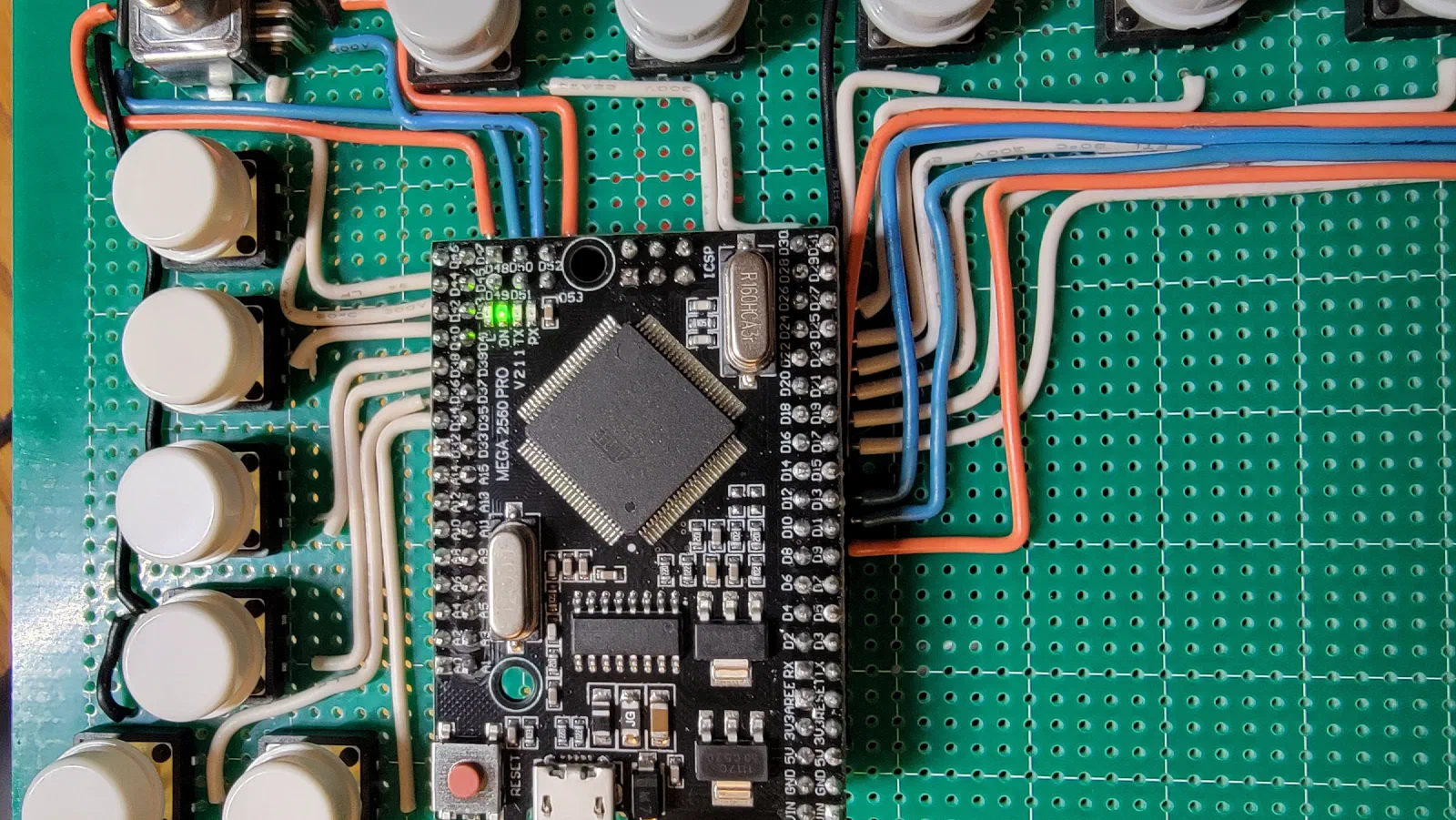
I started with a simple breadboard containing the Mega 2560 Pro Mini and representative GNS 530 controls.
Rather than immediately trying to reproduce every control, the first objective was to establish a basic input architecture and verify that the hardware could communicate with Air Manager.
Result
The breadboard provided a much faster way to experiment with the control interface.
Individual controls could be added, tested, changed, or rewired without having to modify a PCB.
That makes this stage particularly useful for discovering requirements that weren’t obvious during the initial design.
Interfacing With Air Manager
One of the advantages of using Air Manager for this simulator project is that it allows the physical controls to be prototyped without having to develop the entire simulator interface from scratch.
The Arduino hardware provides the physical inputs, while Air Manager provides the connection between those inputs and the simulated aircraft.
This lets me concentrate on the hardware interface.
For the initial prototype, the Mega acts primarily as an input device.
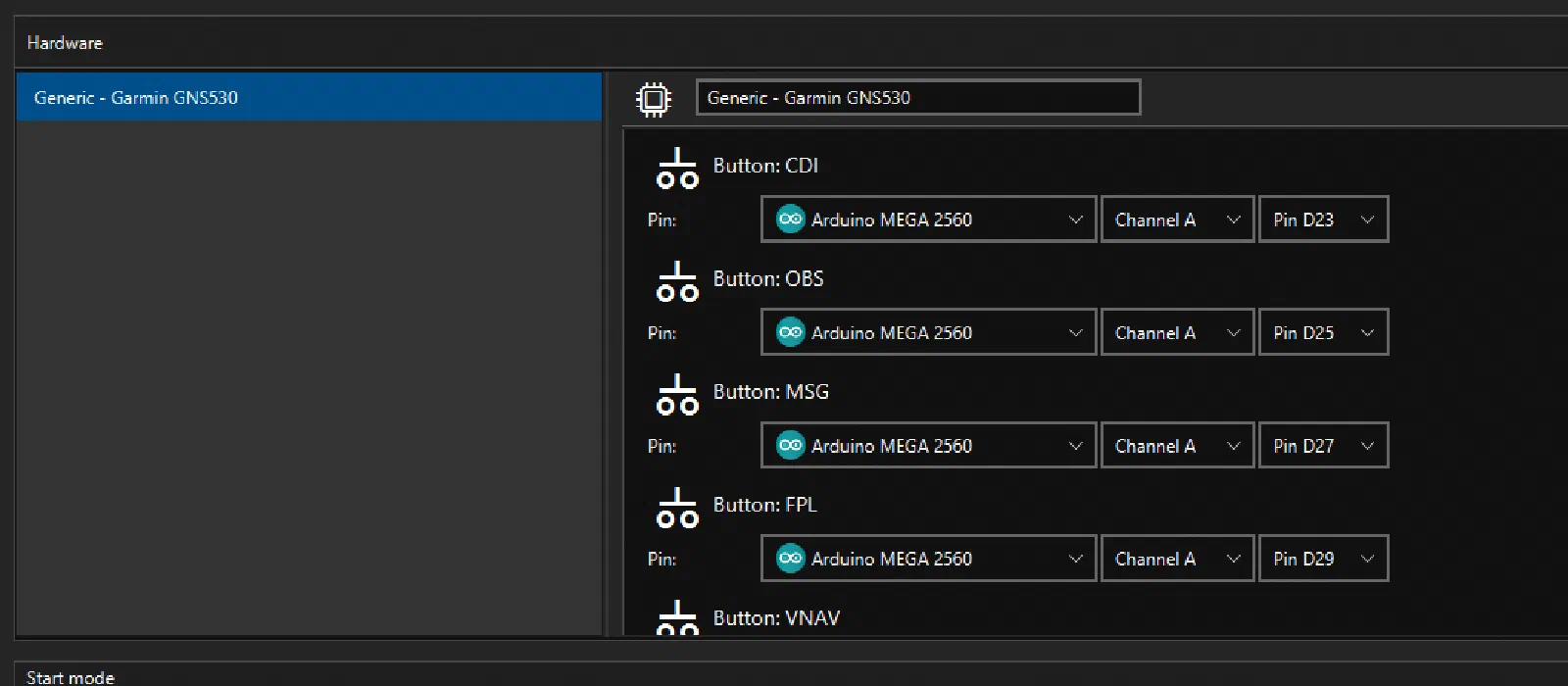
The basic development loop becomes:
Physical Control → Mega 2560 → Air Manager → X-Plane
This is considerably faster than trying to design the final electronics, firmware, and simulator interface simultaneously.
Testing the Rotary Controls
The rotary controls are one of the more interesting parts of the GNS 530 interface.
Unlike a simple pushbutton, a rotary encoder doesn’t simply have an ON or OFF state.
The hardware needs to detect the direction of rotation and translate that into a usable input.
This makes the breadboard particularly useful.
I can test an encoder independently, determine how it behaves electrically, and then experiment with how Air Manager interprets the resulting input.
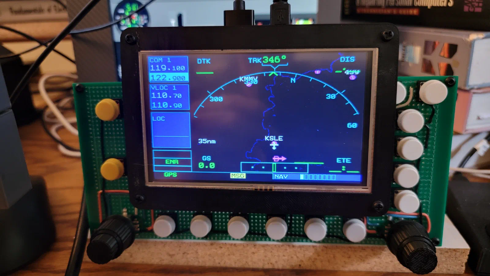
The initial objective isn’t to perfectly reproduce the final GNS 530 controls.
It is to establish a reliable pattern that can later be repeated across the other controls.
Pushbuttons and Switch Inputs
The GNS 530 also contains a number of pushbuttons.
These are considerably simpler from an electrical standpoint, but the breadboard still provides an opportunity to test how they should be connected.
Each button essentially becomes a digital input to the Mega.
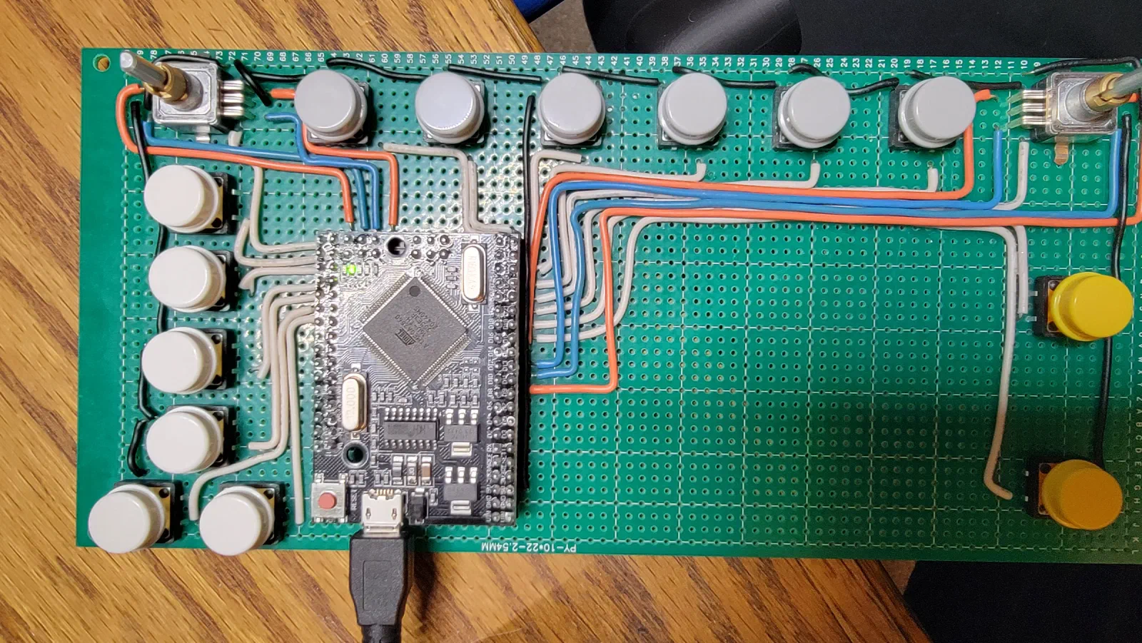
Testing the buttons individually also provides a chance to establish consistent wiring conventions before the design becomes more complicated.
This matters because the final unit will have a significant number of connections packed into a relatively small space.
From Prototype to Requirements
One of the main purposes of this prototype is to turn assumptions into actual requirements.
Rather than saying:
“The GNS 530 probably needs about this many inputs.”
I can now start documenting exactly what the hardware requires.
| Control Type | Prototype Input | Final Hardware |
|---|---|---|
| Rotary encoder | Digital inputs | TBD |
| Pushbutton | Digital input | TBD |
| Additional controls | Digital inputs | TBD |
| Status/interface signals | TBD | TBD |
The table will evolve as the prototype develops.
The final goal is to have a clear I/O map before beginning the custom PCB design.
What the Breadboard Reveals
Breadboarding also exposes problems that aren’t obvious in a CAD model.
With the controls physically connected, wiring quickly becomes part of the engineering problem.
A prototype that looks simple electrically can become surprisingly messy once multiple encoders and buttons are connected.
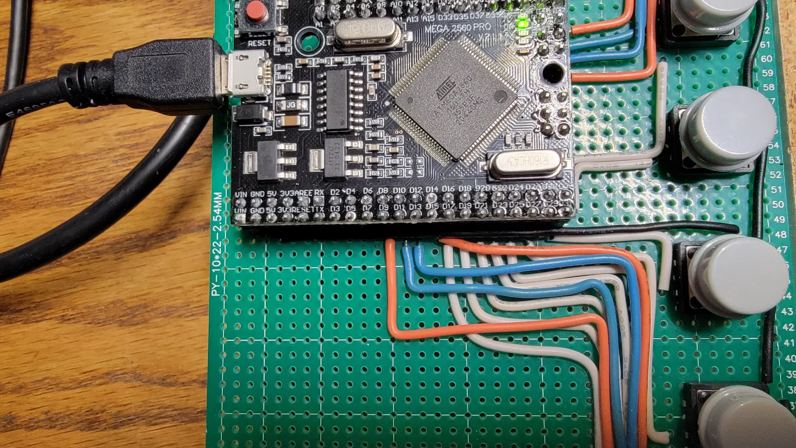
This is exactly the kind of information I want to capture during this phase.
The eventual PCB should eliminate much of this wiring, but I don’t want to design the PCB until I understand what the wiring is actually doing.
Result
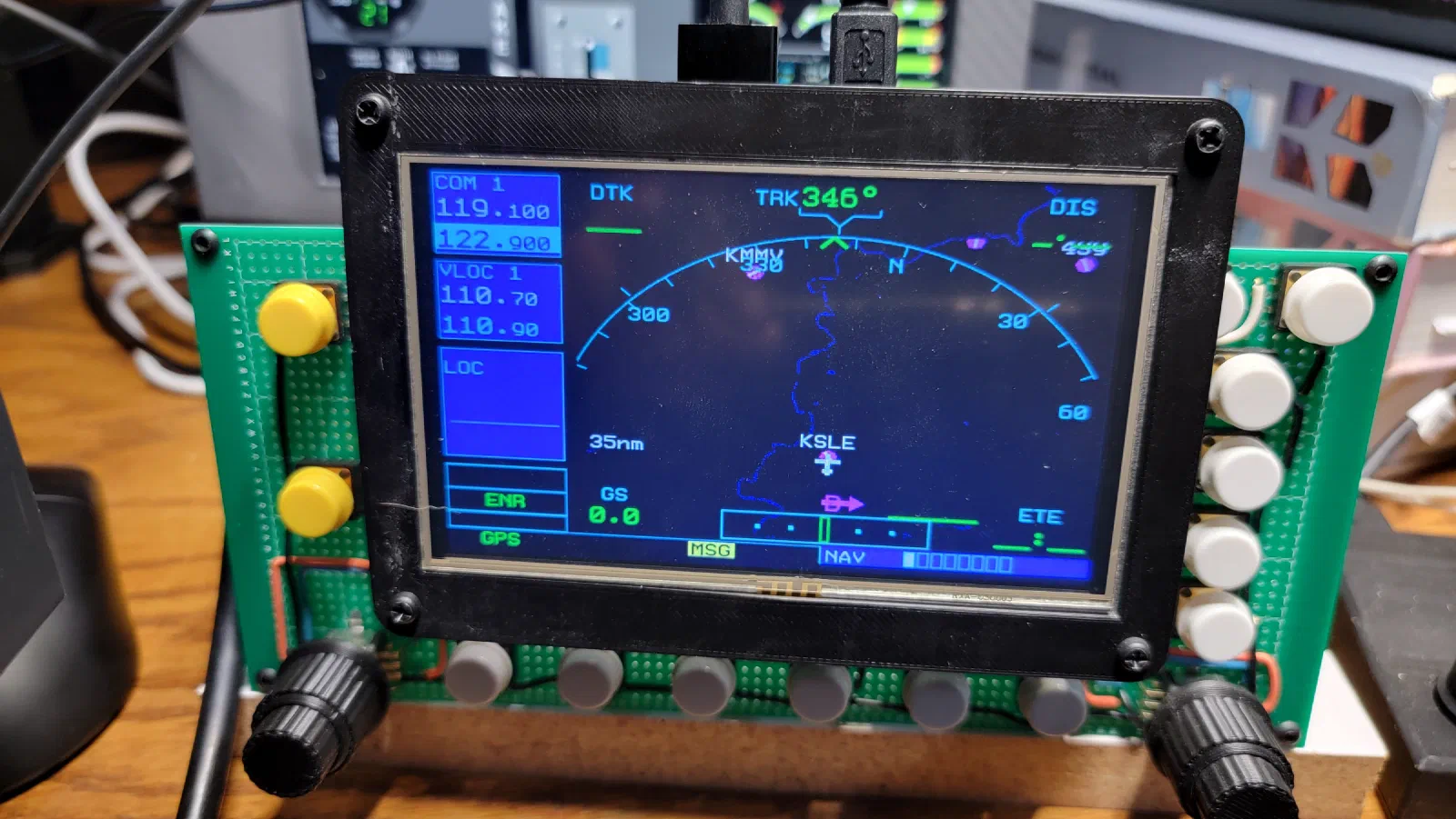
The first GNS 530 breadboard doesn’t look particularly impressive.
That’s intentional.
This is an engineering prototype, not the finished simulator hardware.
The Mega 2560 Pro Mini provides enough I/O to experiment with the control architecture, while Air Manager provides the software connection to the simulator.
More importantly, the prototype establishes a practical development path:
Prototype the control → Verify the interface → Document the requirements → Design the PCB → Build the final hardware
Lessons Learned
1. Prototype before committing to the PCB
The breadboard makes it inexpensive to discover problems before they become PCB problems.
2. I/O requirements need to be measured
The number of physical controls is only part of the equation. Encoders, switches, and other interfaces can affect the required I/O considerably.
3. Wiring becomes a design problem
Even a relatively small number of controls can produce a surprisingly large wiring harness.
The final PCB should address this rather than simply transferring the breadboard wiring into a permanent installation.
4. The Mega is a development platform
The Mega 2560 Pro Mini is useful because it makes experimentation easy.
It isn’t necessarily the architecture I want for the final GNS 530 hardware.
The final design may use a custom microcontroller board with dedicated connectors and a cleaner electrical architecture.
5. Software abstraction speeds up hardware development
Using Air Manager allows the physical controls to be tested without building a complete custom simulator software stack.
That keeps the focus of this stage where it belongs: figuring out the hardware.
What’s Next?
The next stage will be to expand the prototype beyond the initial controls and build a more complete GNS 530 input set.
That should provide enough information to finalize the I/O requirements and start thinking about the physical electronics architecture.
From there, the project can move from:
Breadboard prototype
→ Complete control prototype
→ I/O definition
→ Custom PCB
→ Final GNS 530 hardware
The breadboard is only the beginning, but it establishes an important foundation for the custom avionics hardware that will eventually become part of the simulator.