Prototype HID Controller
Christopher Edwards
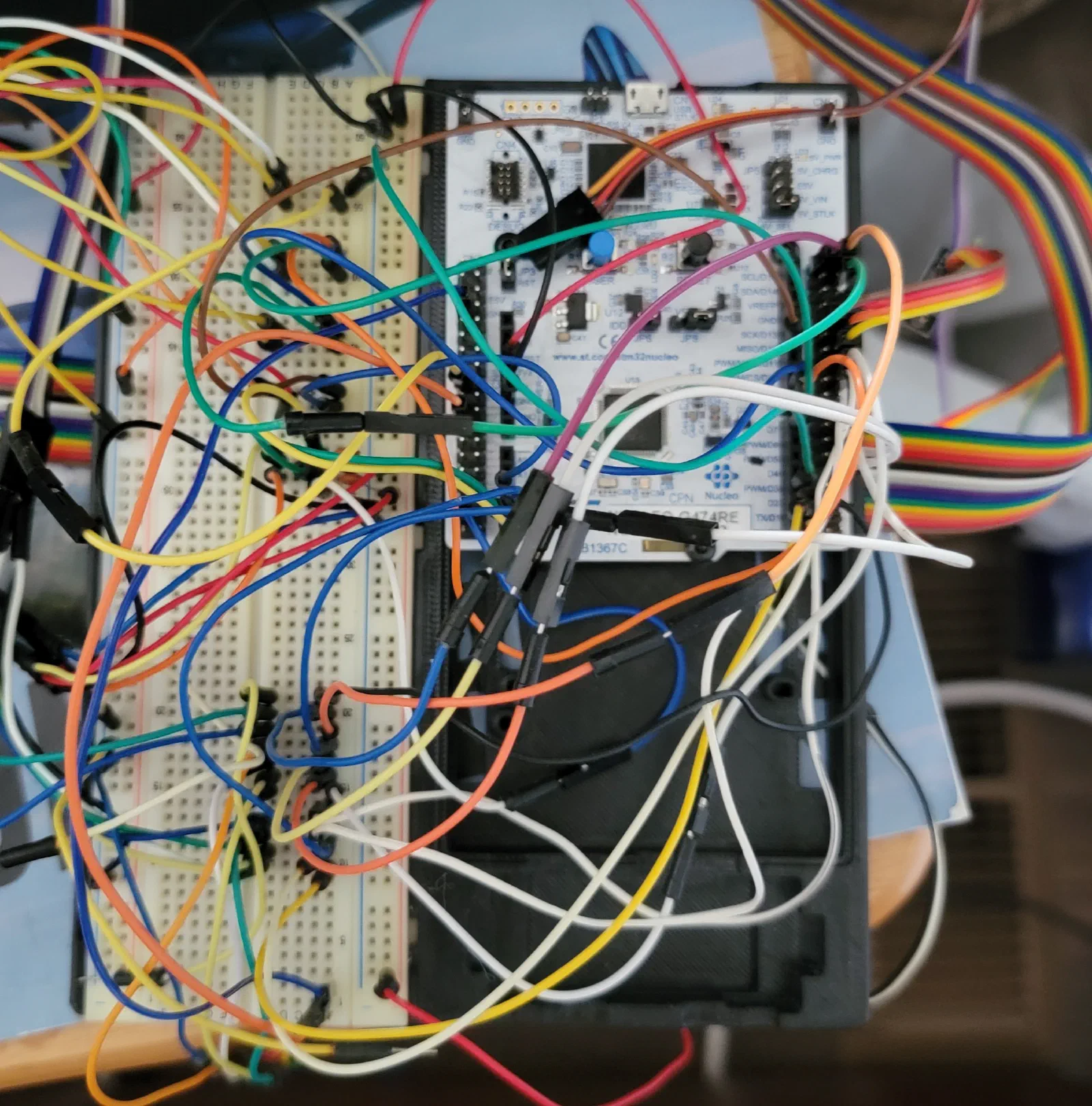
Custom HID Controller
With the basic functionality of the simulator now working, the focus can start shifting from simply getting controls operational to refining the designs into the final system. The early development used readily available development boards and simple interfaces to get the different components working quickly. That approach was useful during prototyping, but the TPM console has now grown beyond what those original controllers were intended to support.
The next step is to begin developing the custom electronics that will eventually replace the prototype hardware.
Initial Concept
The first controller for the TPM console was based around an ATmega32U4. It was a good choice for the initial prototype because USB HID support was readily available and it allowed me to get buttons and other controls communicating with the simulator without spending much time developing the controller hardware.
At the time, the goal was simply to get something working.
As more controls were added, however, the TPM console grew considerably. There are now substantially more inputs to deal with, along with rotary controls, analog inputs, and other hardware that needs to be integrated into the controller.
The ATmega32U4 has served its purpose, but it is no longer a particularly good fit for the direction of the project.
Rather than continuing to expand the original prototype, I decided this was a good point to move toward a dedicated controller.
Choosing the STM32G474RE
The new controller will be based on the STM32G474RE.
I’ve worked extensively with STM32 devices in the past, so this was a fairly natural choice. I already have experience with the development tools and STM32 peripherals, which means I can spend more time working on the actual controller rather than learning a new platform.
The STM32G474RE also provides considerably more capability than the original ATmega32U4 design. This gives the controller room to handle the current TPM console while leaving some flexibility for future expansion.
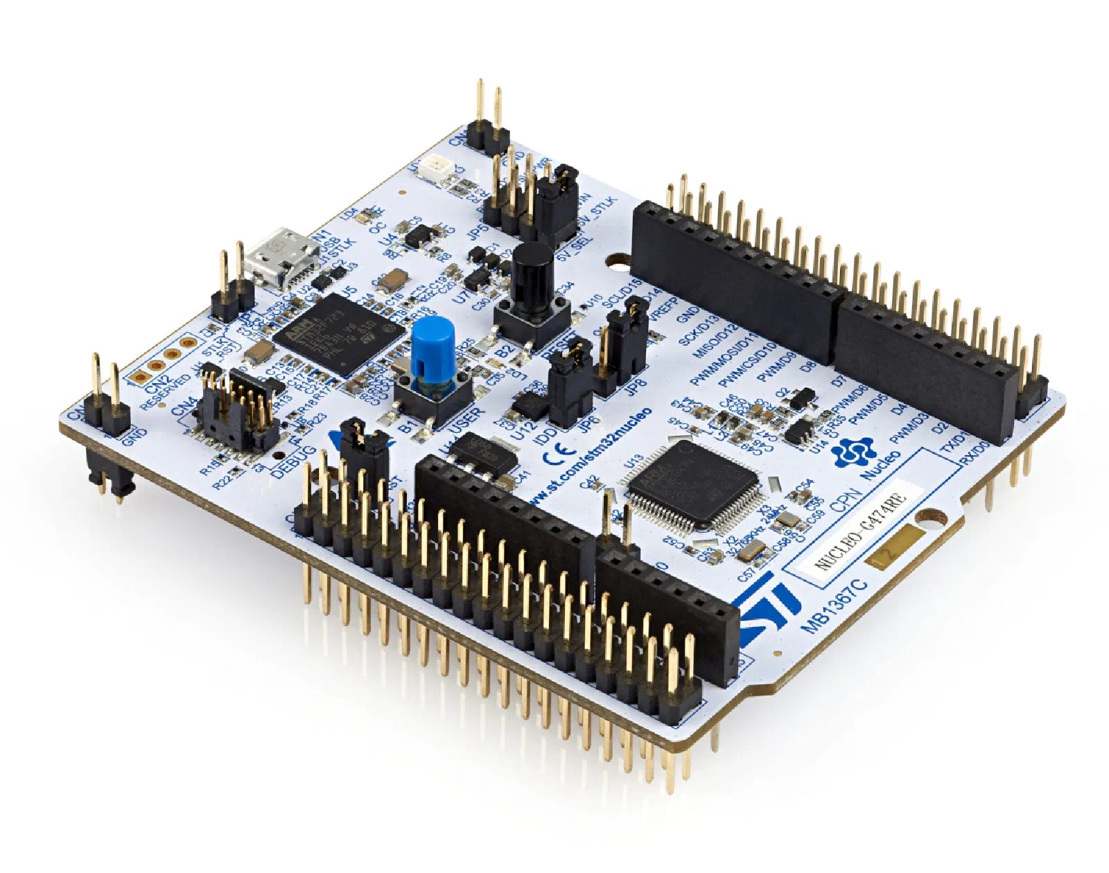
Another advantage is that I already had an STM32G474RE Nucleo board available. This makes it possible to develop the firmware and HID interface before committing to a PCB design.
Prototype
The first step is to use the Nucleo board as the controller rather than immediately designing the custom PCB.
This allows the software and electrical interface to be developed independently from the final board layout. I can connect the existing controls to the development board, establish the USB HID interface, and verify how the different types of inputs need to be represented to the simulator.
[IMAGE PLACEHOLDER — Nucleo board connected to prototype TPM controls]
This also provides a useful opportunity to determine the actual I/O requirements for the final board.
The controller needs to handle more than just simple switches. The existing hardware includes pushbuttons, switches, rotary controls, and analog inputs. Some of the controls also have corresponding indicators or other outputs.
Rather than designing the PCB around an assumed configuration, I can use the prototype to establish what is actually required.
HID Interface
One of the main goals of this stage is to develop a common HID interface for the simulator controls.
The original ATmega32U4 controller was primarily intended to get individual controls working. The new controller will be designed around the TPM console as a complete system.
The basic interface will be:
Controls → STM32G474RE → USB HID → Simulator
The firmware will be responsible for reading the various inputs, maintaining their state, and presenting them to the computer through USB.
This also provides a good opportunity to establish a consistent software architecture before the final hardware is designed.
Testing
Using the Nucleo board for the initial development should make testing considerably easier.
The firmware can be developed and tested while the hardware remains relatively easy to modify. If an additional input is required or an assumption about the interface turns out to be wrong, it is much easier to change the prototype than it would be after the PCB has been designed.
The initial testing will focus on the basic building blocks:
- Digital inputs
- Switch debouncing
- Rotary encoders
- Analog inputs
- USB HID communication
- Input state management
- Timing and update rates
Once these pieces are working, the firmware can be used as the basis for the custom controller.
Refinements
Moving to a custom controller isn’t just about replacing the microcontroller.
The original prototype was intentionally built around whatever was quickest to get operational. As the project has developed, that has resulted in a collection of different approaches to connecting and handling the controls.
The final controller is an opportunity to clean that up.
The goal is to have a dedicated interface for the controls, fewer temporary connections, and a controller designed around the actual requirements of the simulator.
This is also where some of the earlier mechanical designs can start influencing the electrical design. The various control build logs have established how the switches, potentiometers, encoders, and other controls physically work. The custom PCB can now be designed around those actual components rather than around a generic development board.
Final Design
The custom PCB will come after the STM32-based prototype has been tested.
I don’t want to design the final board until the firmware and I/O requirements are better understood. The Nucleo board provides a convenient way to prove the concept first and should reduce the amount of debugging required once the custom hardware is built.
The eventual goal is a controller that can serve as the central interface for the TPM console and provide a foundation for the other simulator controls as the project continues to grow.
Next Steps
The immediate goal is to get the STM32G474RE running as a USB HID controller and begin moving the existing TPM controls over to it.
Once the basic HID interface is working, I can start defining the complete I/O configuration and firmware architecture.
That information will then be used to design the first custom PCB.
This is the beginning of the transition from the collection of prototypes that got the simulator working to the electronics that will become part of the final system.