Throttle Propeller Mixture & Trim
Christopher Edwards
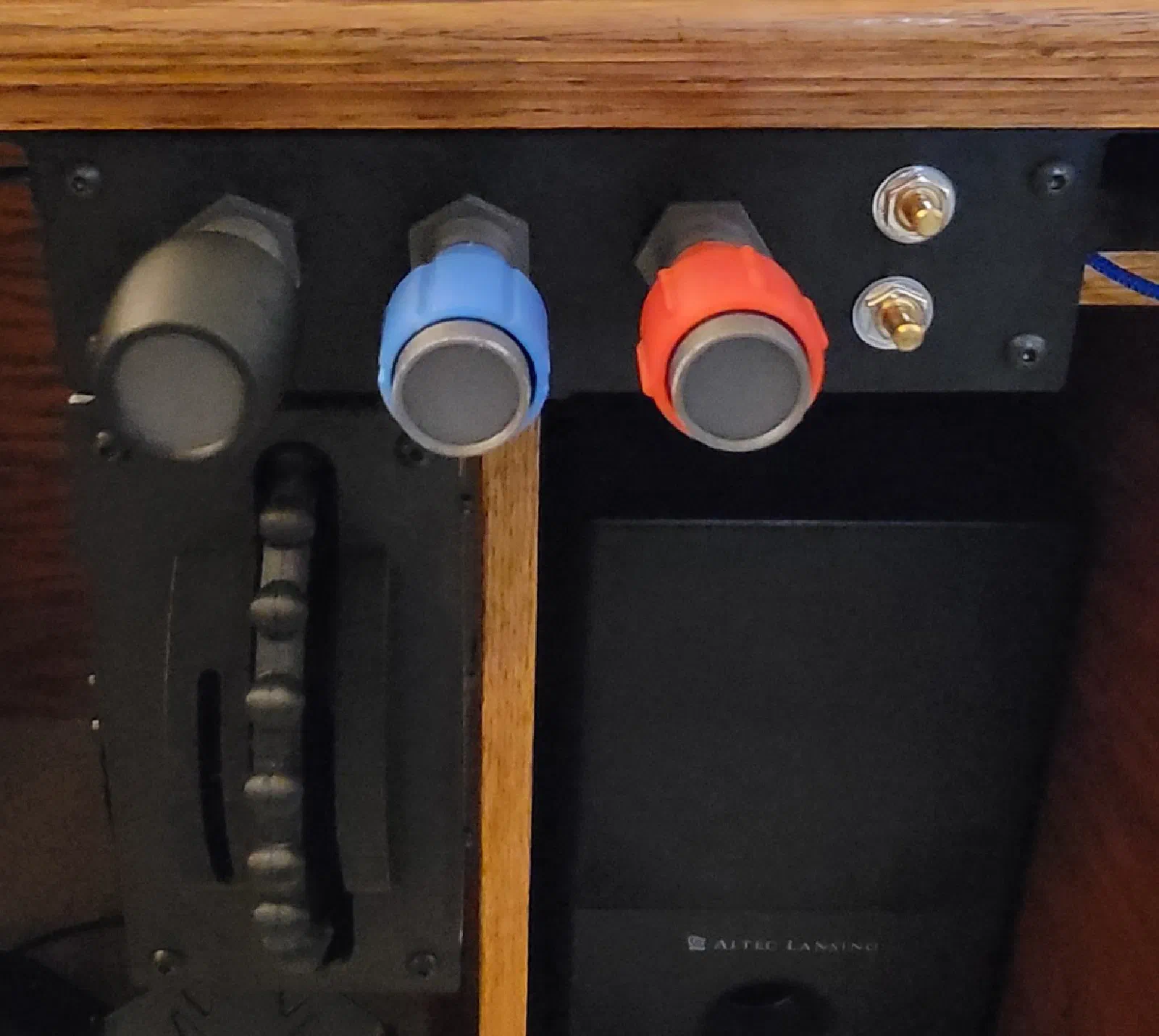
Building the Throttle, Prop, Mixture (TPM) / Trim Controller
Extending the Switch Box Firmware with Analog Inputs and Magnetic Position Sensing
Project: Cessna 172 Flight Simulator Build Stage: Initial TPM / Trim Controller Prototype Hardware: ATmega32U4, AS5134 magnetic encoder Firmware: Extension of the Switch Box codebase Date: September 2026
Project Journal
With the switch box prototype established, the next piece of cockpit hardware was the Throttle, Prop, Mixture (TPM) / Trim Controller.
The goal of this prototype is to start building a physical control unit that combines the engine controls with the trim interface found in the Cessna 172 cockpit.
The initial device includes:
- Throttle control
- Propeller control
- Mixture control
- Two analog lighting controls
- Elevator trim interface
- AS5134 magnetic position sensor for trim
- ATmega32U4 USB interface
This build is also the first opportunity to significantly expand the switch-box firmware.
The switch box was primarily concerned with discrete inputs—switches and buttons. The TPM/Trim controller introduces continuous-position inputs, requiring the firmware to handle analog axes as well as a magnetic position sensor.
Starting With the Switch Box
One of the goals of this project is to avoid creating a completely separate firmware implementation for every piece of simulator hardware.
The switch box already provided a working foundation for the ATmega32U4, including the USB HID interface and basic input handling.
Rather than throwing that work away, the TPM/Trim controller builds on it.
The existing codebase provides the starting point for adding the new input types required by the TPM controller.
This makes the TPM/Trim device both a hardware prototype and a test of how the simulator’s control firmware can evolve.
The TPM Controls
The heart of the device is the three engine controls:
- Throttle
- Propeller
- Mixture
These controls need to provide continuous position information to the simulator.
Unlike a switch, there isn’t simply an ON or OFF state.
The controller needs to determine where each control is within its physical range and convert that position into a USB HID axis.
The basic signal path is:
Physical Control → Analog Input → ATmega32U4 → USB HID → X-Plane
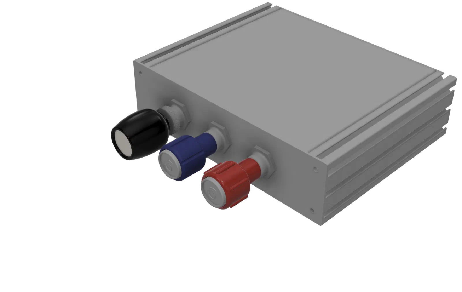
The initial prototype uses analog inputs to explore this approach before committing to the final electronics and mechanical design.
Adding Analog Inputs to the Existing Codebase
The first significant firmware change was adding analog inputs to the existing switch-box code.
The basic switch-box input path was relatively simple:
GPIO → Digital State → HID
The TPM controls require something different:
ADC → Raw Analog Value → Processing → HID Axis
The ATmega32U4’s ADC provides the raw position information.
The firmware then has to turn that raw value into a useful simulator axis.
This required expanding the input-handling portion of the existing codebase while keeping the USB HID portion of the project largely intact.
Keeping the Analog Inputs Reusable
Although throttle, propeller, mixture, and lighting all have different functions in the simulator, they share the same basic electrical interface.
That makes them a good candidate for a common analog-input implementation.
The firmware can read an analog input and then apply the configuration associated with that particular control.
That configuration can eventually include things such as:
- Minimum value
- Maximum value
- Output range
- Direction
- Calibration
- Dead zone
This keeps the hardware-specific details separate from the general input-processing code.
It also means that adding another analog control later shouldn’t require writing an entirely new ADC implementation.
Throttle, Prop, and Mixture
The TPM controls are the primary reason for adding analog support to the controller.
Each control is connected to its own analog input and represented as an independent simulator axis.
At this stage, the goal is not to perfectly reproduce the final throttle quadrant.
The prototype is intended to answer the more fundamental questions first:
- Does the analog interface provide enough resolution?
- How should the physical travel map to the simulator?
- How should calibration work?
- How should the firmware handle the inputs?
- Does the control feel natural when used with the simulator?
Once those questions are answered, the mechanical design can be refined around the electronics.
Adding the Lighting Controls
Two additional analog knobs are included in the prototype for lighting control.
These provide another useful test of the analog-input implementation.
They also demonstrate that the TPM/Trim controller isn’t limited to the three primary engine controls.
The same underlying analog-input handling can support additional cockpit controls without fundamentally changing the USB interface.
The Trim Interface
The other major part of this project is the trim controller.
Rather than using a conventional potentiometer, the prototype uses an AS5134 magnetic rotary position sensor.
This introduces a different type of position input into the system.
The basic interface is:
Trim Control → Magnet → AS5134 → ATmega32U4
The AS5134 provides magnetic position sensing, allowing the controller to determine the rotational position of the trim mechanism without relying on a conventional resistive potentiometer.
For this prototype, that makes it an interesting alternative approach to sensing trim position.
Interfacing the AS5134
Unlike the TPM controls, the trim position does not come directly from the ATmega32U4’s ADC.
The microcontroller communicates with the AS5134 and obtains the encoder position from the sensor.
This means the firmware now has to deal with another class of input device.
The trim interface needs to handle:
- Sensor initialization
- Position acquisition
- Encoder direction
- Zero/reference position
- Mechanical range
- Position conversion
The important architectural point is that the sensor-specific code can remain separate from the simulator-facing HID code.
Once the firmware has converted the encoder position into a usable control value, the HID layer can treat it as another axis.
From Encoder Position to Trim Axis
The AS5134 reports a rotational position.
The simulator needs a control value representing trim position.
The firmware therefore acts as the translation layer between the two.
Conceptually:
AS5134 Position
↓
Zero / Offset
↓
Direction
↓
Usable Mechanical Range
↓
HID Trim Axis
This is also where calibration will eventually become important.
The sensor’s zero position and the physical center of the trim mechanism don’t necessarily have to be identical.
Being able to establish that relationship in software gives more flexibility to the mechanical design.
One Controller, Multiple Input Types
The TPM/Trim controller now brings several different input types together.
| Input | Type | Simulator Function |
|---|---|---|
| Throttle | Analog | Engine control axis |
| Propeller | Analog | Engine control axis |
| Mixture | Analog | Engine control axis |
| Lighting 1 | Analog | Lighting control |
| Lighting 2 | Analog | Lighting control |
| Trim | Magnetic encoder | Trim axis |
The important part is that they can all ultimately be handled by the same ATmega32U4 USB device.
This is where extending the switch-box codebase starts to pay off.
The TPM/Trim controller doesn’t need an entirely new USB architecture. It can use the same HID foundation while adding the input-processing capabilities required by the new controls.
Initial Firmware Results
The first goal for the firmware is relatively simple:
Get reliable physical position information from the controls and make it available to the simulator.
The existing switch-box firmware already provides the USB foundation.
The TPM/Trim prototype adds:
- Analog input acquisition
- Analog axis processing
- Multiple simultaneous analog inputs
- AS5134 position acquisition
- Magnetic encoder processing
- Trim axis output
[IMAGE PLACEHOLDER — Debugging the TPM/Trim inputs]
This is still prototype firmware.
The intent is to establish a working foundation that can be refined as the mechanical design develops.
Why Build the TPM/Trim Controller This Way?
The project is deliberately being developed incrementally.
The switch box provided a working digital-input platform.
The TPM/Trim controller builds on that platform and introduces analog and magnetic position inputs.
This approach allows the hardware and firmware to evolve together.
Instead of trying to design the final controller immediately, each prototype can answer a specific set of engineering questions before the design moves forward.
Lessons Learned
The main lesson from this prototype is that moving from switches to physical controls changes the firmware requirements considerably.
A switch only requires knowing its state.
A throttle or trim control requires knowing where it is.
That introduces additional requirements for:
- Calibration
- Scaling
- Position processing
- Input resolution
- Update rates
- Mechanical limits
The AS5134 adds another interesting dimension by providing position information through a magnetic sensing system rather than a traditional analog input.
This makes the TPM/Trim controller a useful step toward a more general simulator-control firmware architecture.
Next Steps
The next iteration will focus on refining the TPM/Trim controller itself.
Planned work includes:
- Refining the throttle mechanism
- Refining the propeller and mixture controls
- Improving analog calibration
- Testing different input ranges
- Refining the AS5134 trim interface
- Establishing reliable trim centering
- Improving the mechanical trim mechanism
- Cleaning up the prototype wiring
- Continuing to evolve the common firmware
- Moving toward custom electronics and a PCB
Looking Ahead
The TPM/Trim controller is an important step in the simulator project because it moves beyond individual switches and starts creating the physical controls that are used continuously during flight.
The switch box established the foundation.
The TPM/Trim controller builds on that foundation by adding analog control inputs and magnetic position sensing.
The ATmega32U4 provides a convenient platform for experimenting with those interfaces, while the existing switch-box codebase gives the firmware a head start.
As the prototype matures, the goal is to turn what started as a collection of development hardware into a purpose-built TPM/Trim controller that fits naturally into the larger Cessna 172 simulator.