Vernier Control
Christopher Edwards
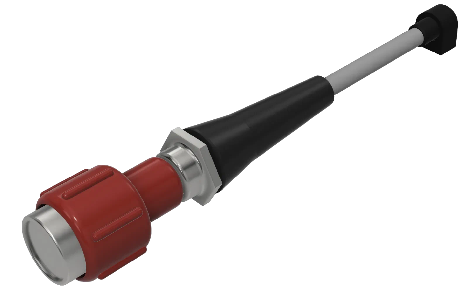
Refining the Vernier Controls in the TPM Assembly
Project Journal / Engineering Build Log
The vernier controls are an important part of the TPM (Throttle, Propeller, Mixture) assembly. They provide the combination of coarse and fine adjustment found on many aircraft engine controls, allowing the pilot to quickly move a control through its range and then make precise adjustments.
The first version of the TPM assembly established the basic mechanism, but continued use revealed a weakness in the material used for the control shafts. This iteration focused on making the shafts more robust while retaining the existing vernier mechanism.
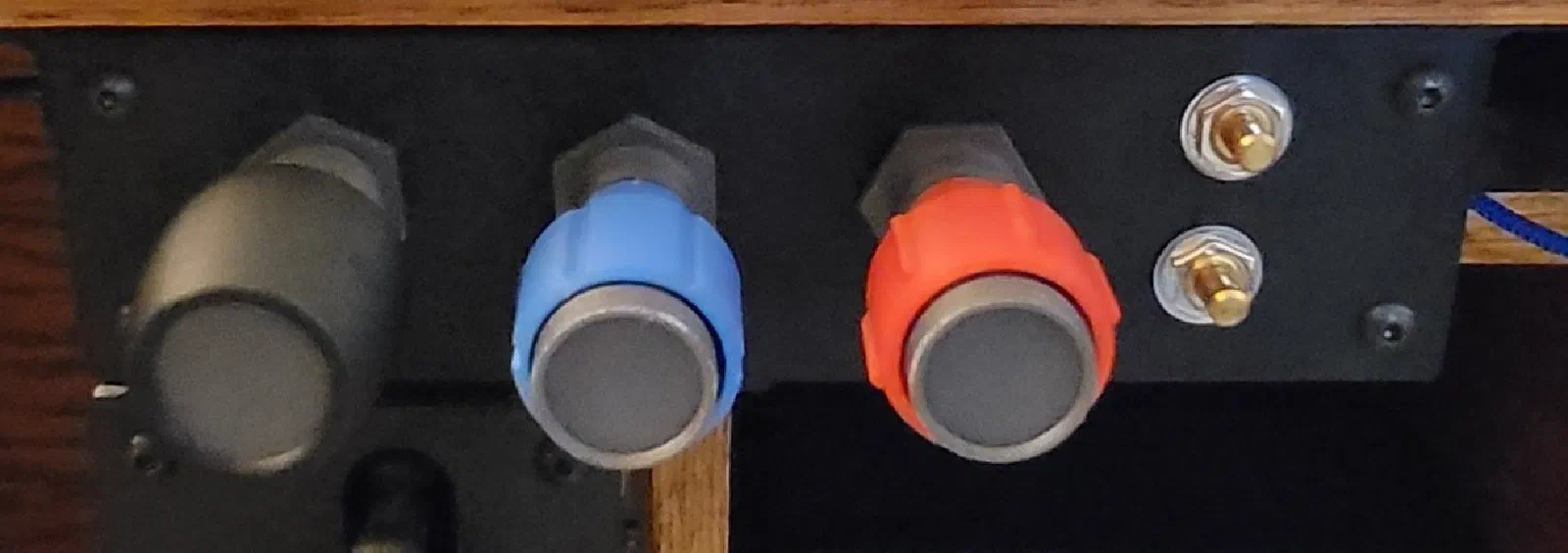
How the Vernier Control Works
The TPM vernier controls provide two modes of adjustment.
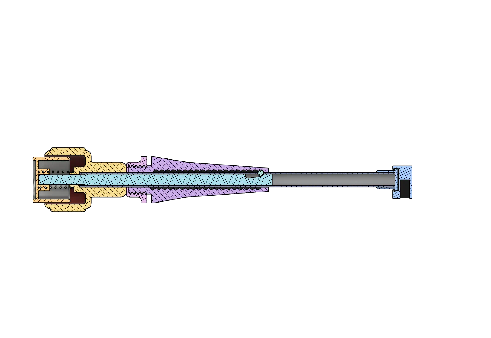
A spring-loaded button releases the mechanism for coarse adjustment. With the button pressed, the control can be pushed or pulled through its larger range of movement.
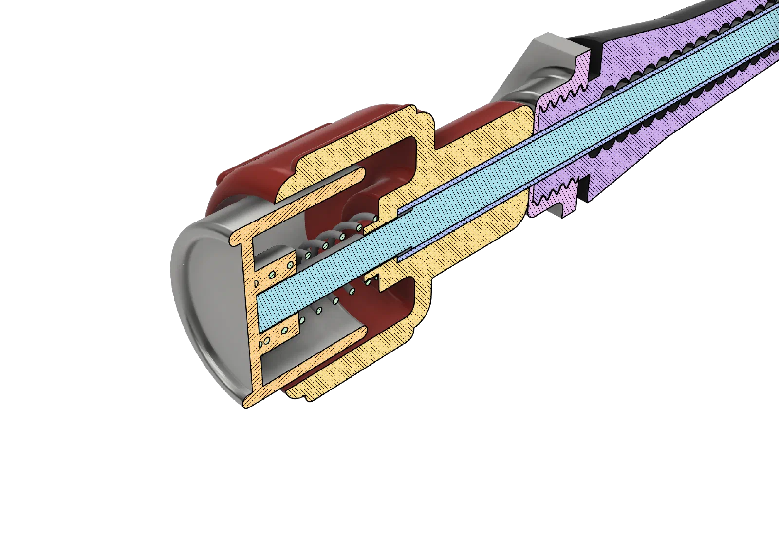
Releasing the button allows the spring to return the mechanism to the vernier position. The control can then be rotated to make small, precise adjustments.
Button pressed → coarse adjustment
Button released → fine adjustment
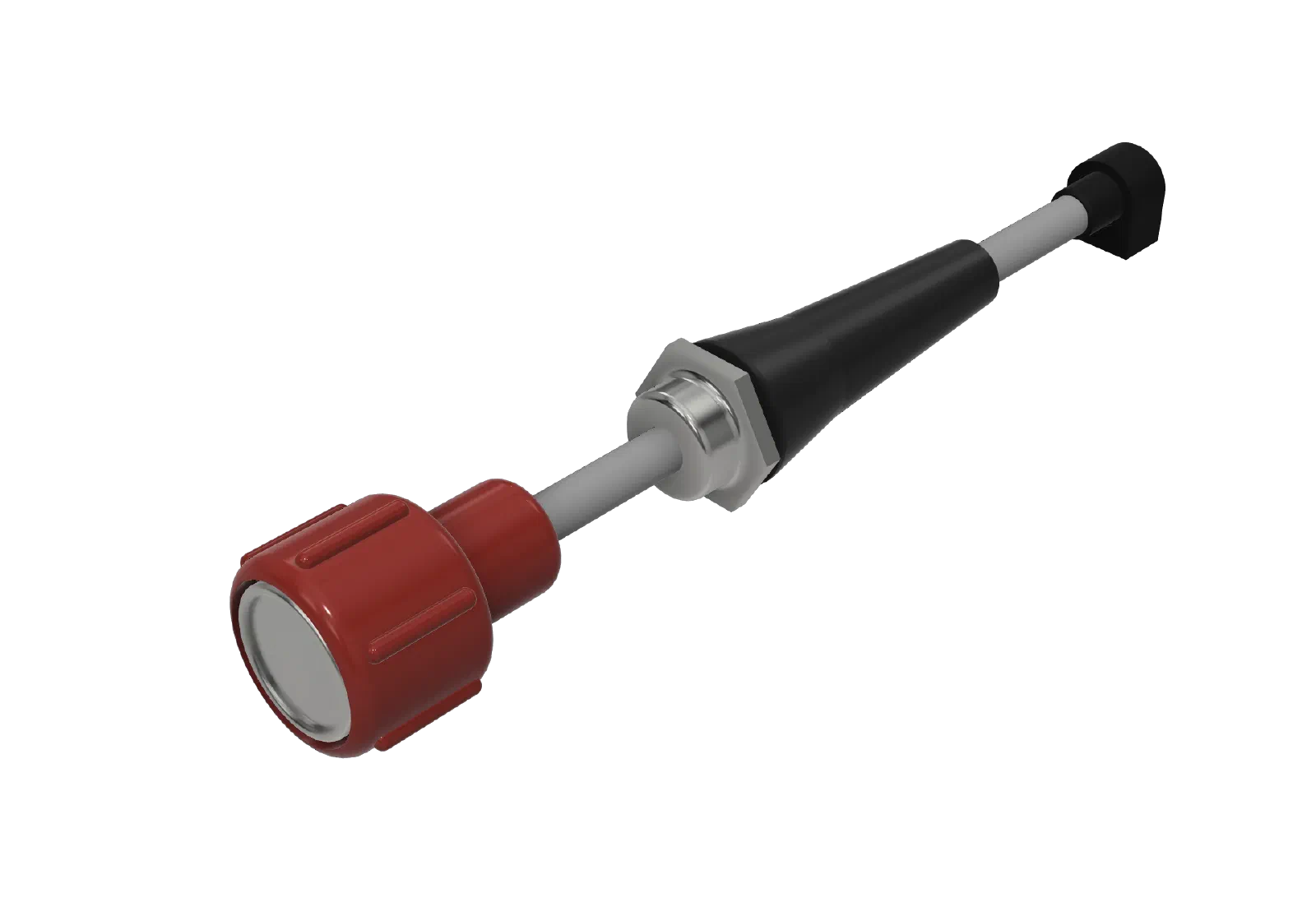
This combines the speed of a conventional push/pull control with the precision of a vernier adjustment.
For the TPM controls, this provides a useful physical interaction. A large throttle, propeller, or mixture change can be made quickly by pushing or pulling the control, while smaller adjustments can be made by rotating the knob.
The First Prototype
The initial design used thin tubing for the vernier shafts.
The tubing was a convenient choice for the prototype. It was easy to work with and provided a simple connection between the external control and the mechanism inside the assembly.
During normal operation, the tubing performed adequately. The push/pull movement for coarse adjustment worked as intended, and the rotational movement of the vernier was not a significant problem.
The weakness became apparent when the control was extended.
The Problem: An Easily Damaged Extended Shaft
When the vernier control was pulled out, a longer section of the tubing was exposed beyond the main assembly.
In this position, the unsupported tubing could be bent relatively easily if the control was bumped or subjected to a sideways force.
Because the tubing was thin, the result could be a permanent kink rather than simply temporary flex.
This created a durability problem. The control could function correctly during normal operation but still be vulnerable to damage during handling.
For a simulator control intended to be operated repeatedly, the exposed shaft needed to be considerably more robust.
Revising the Shaft
The primary change was replacing the thin tubing with a more substantial shaft.
The new shaft was selected to provide significantly greater resistance to bending, particularly when extended.
The goal was not to redesign the vernier mechanism itself. The existing mechanism already provided the desired coarse and fine adjustment. The change was focused specifically on the shaft that connects the user-operated control to that mechanism.
The revised design maintains the same basic movement while providing a stronger and more durable mechanical connection.
Updating the 3D-Printed Components
Changing the shaft dimensions required corresponding changes to the 3D-printed components.
The shaft openings, supports, and clearances had to be adjusted to accommodate the new shaft.
This is a typical part of the iterative prototyping process. The original design established the mechanism, while actual use revealed a durability issue that needed to be addressed in the mechanical design.
Testing the Revision
The revised controls were tested in both operating modes.
With the button pressed, the control could still be pushed and pulled through its full range as intended.
With the button released, the vernier continued to provide the desired fine rotational adjustment.
The most important test was the extended position.
The revised shaft was considerably more resistant to bending, reducing the likelihood of damage from an accidental sideways load.
The result is a more durable control without changing the fundamental way the vernier operates.
Lessons Learned
Prototype materials are not always suitable for the finished design
The original tubing was adequate for proving the vernier concept. Its limitations only became apparent once the control was being used as a physical simulator interface.
The mechanism itself was working; the exposed shaft simply needed a more durable material.
Extended components need to account for accidental loads
The extended position changed the mechanical requirements of the shaft.
When the tubing was supported inside the assembly, its flexibility wasn’t particularly problematic. Once extended, however, the exposed section became much more vulnerable to sideways forces.
This is an important consideration for future designs: exposed components need to be evaluated not only for their intended loads, but also for how easily they can be damaged during normal handling.
Mechanical feel matters
A physical simulator control is more than its electronic input. The mechanism should feel solid and predictable when operated.
The revised shaft improves the durability of the control while retaining the existing coarse/fine interaction provided by the spring-loaded vernier mechanism.
Next Steps
The revised vernier controls address the primary weakness found in the original design: the thin tubing was too easy to bend and kink when the control was extended.
The updated shaft improves durability without requiring a fundamental change to the vernier mechanism.
The next iterations will continue to focus on the balance between mechanical feel, durability, and ease of manufacturing as the TPM assembly moves from prototype toward a more finished simulator control.